From a very early age, children are warned about the dangers of electricity. Later, in physics lessons, they learn that current strength greater than 0.1A or 100mA is deadly. But many people confuse this concept and tension.
Before getting acquainted with the design of a device that can protect against the destructive effects of electricity, you need to refresh your memory of its basic concepts. The flow of electric charges, thanks to the ability to create thermal, electromagnetic, electrochemical interactions, is an energy carrier that has fundamentally determined the development of mankind.
But, when passing through the human body, these interactions adversely affect the structure of cells at the molecular level, causing their death. The nervous system, which works on the principle of the exchange of electrical charges, also becomes paralyzed. The more electrons pass through the conductor, the greater the current strength, the greater its damaging effect.
Visualization of electricity
Visually, this force can be compared with the volume of moving water, while voltage with a difference in levels. A thin stream falling from a large vertical distance will not have a noticeable effect on the human body, compared to a meter-high stream that knocks you off your feet.
Voltage U creates an electric current directly proportional to U, and its strength I, according to Ohm's law, is inversely proportional to the resistance R of the power source, supply wires and the conductor itself, which is the human body at the time of injury, I=U/R. Since the network voltage is standard, its resistance is very low, the degree of the damaging effect of electricity depends on the resistance of the body, dry skin, and the presence of shoes.
Measuring leakage causing damage.
In an ideal two-wire system, the currents in the phase and neutral wires are equal: IL = IN. If somewhere in the circuit a wire comes into contact with ground through poor insulation, or the human body, then IL= IN+IΔn, where IΔn is the leakage current that causes damage or ignition of the cable. Accordingly, IΔn is equal to the difference between the input and output currents: IΔn= IL-IN.
Measuring this difference (English different) using a differential transformer made it possible to create a residual current device (abbreviated RCD), which opens the circuit, turning off the voltage if IΔn exceeds a value dangerous to health, or a fire-hazardous current is more than 100 mA.
A differential current transformer has two primary windings (coils), connected in different directions, and a secondary winding, which is connected to the actuator of the tripping mechanism. If in the primary coils IL = IN, then the magnetic flux in the toroidal core will be mutually compensated ФL = ФN, accordingly, no electromotive force will be induced on the secondary winding, there will be no current and its effect on the electromagnetic relay of the switch.
Device activation moment
In the event of a leak IL> IN, which leads to an imbalance of magnetic fluxes, ФL> ФN, and their difference, due to electromagnetic induction, will affect the secondary coil, a current IΔ>0 will appear in it, turning off the protective switch.
Thus, the principle of operation of the RCD is to trigger the tripping mechanism (splitter) when comparing the input and output currents, if the excess of their difference is higher than a set value, which is called the set point. Due to the fact that there are current losses caused by electromagnetic radiation, capacitor effect, static discharge, and also because the insulation is not perfect, the setting is taken above the zero value and depends on the application of the protective devices.
This principle of measuring differential current is also valid for three-phase voltage. In this case, four primary windings are used: three phase and one zero, and in an ideal system the sum of all currents is zero. When there is a leak on one of the phase wires, the balance is disrupted and IΔ occurs, causing the protection to operate.
Rated breaking current (set)
For electrical line cables, according to the PUE, a loss value of 0.01 mA per meter of wire is accepted, and for electrical appliances a loss coefficient of 0.4 mA per load Ampere is applied.
Therefore, to connect a relatively small load using short wires, use the smallest possible setting from a number of unified values of the breaking rated differential current IΔn, which is indicated on the RCD body: 10; thirty; 100; 300;500 mA.
For example, to connect a boiler, sockets, lighting in the bathroom, where the probability of damage is high due to high air humidity and wet surfaces, IΔn=10mA is used. Also, this setting is suitable for the kitchen or electrification of the basement, garage. For the entire house, you need to choose a residual current device with IΔn=30mA, in order to avoid false alarms due to the large number of consumers over a significant network length.
To ensure fire safety of long-distance power networks, set values above 100 mA are used. For different groups of consumers, it is possible to connect several RCDs in parallel with different differential tripping currents. Also common is the sequential circuit of RCDs with different settings to provide selective protection.
Practical use
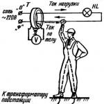
To make the principle of operation of the RCD more clear, it is necessary to consider options for its practical use. If a two-wire power system is used, if the internal circuit of the electrical device fails and dangerous voltage appears on its body, when touching it or a bare live wire, the current will flow through the human body into the ground, thereby disturbing the balance of currents in the differential transformer, due to which the resulting IΔ will turn off the power.

The victim will receive a shock due to the short-term effect of a current exceeding the setting, the value of which will depend on the sum of the resistances of the skin, body tissues, shoes, and floor.
Humidity and contact area are also significant, so the injury rate and depth of shock depend on the conditions in each specific case, but the degree of damage is not fatal due to the short-term impact of the damaging factor, due to the high speed of the RCD.
Provided that an additional third grounding conductor PE is used, if the insulation inside the electrical appliance breaks down, damage will not occur at all, since at this moment, when a leakage current appears, the RCD will immediately trip. Without its use, although damage will not occur due to the grounding of the case, leakage currents are dangerous due to their heat generation, which can lead to further destruction of the electrical device and even provoke its ignition, leading to a fire.
It is believed that at a current greater than 100 mA, enough heat is released at the point of insulation breakdown to heat the contacting materials to the point of melting and ignition.
Therefore, RCDs, in addition to protection against fatal electric shock, are also successfully used to ensure fire safety of the network. Obviously, this function is performed by RCDs with any setting, but it must be remembered that protection devices with IΔn>100mA are used only to prevent fires due to leakage currents in insulation breakdowns.
Important
If the output neutral wire of the RCD comes into contact with ground, grounding or input zero, there will be a false operation of the protection.
Since the RCD does not protect against short circuits and overcurrents, it must be installed together with a circuit breaker.
The performance of the RCD should be periodically checked using the “Test” button.
Introduction
Special electrical devices have been developed to protect people and animals. They are called a residual current device, abbreviated as RCD. The RCD protects against electric shock when touching live equipment. Protection occurs both through direct and indirect contact with live equipment. In addition to this task, the RCD is used to monitor the insulation condition of electrical wiring. This provides additional protection of the room from fire. Let's look at the functions of a residual current device (RCD) in more detail.
RCD functions
The RCD protects humans and animals from electric shock when touching the housings of electrical appliances that are energized.
Conductive housings and individual elements of equipment and devices may be live. This is definitely an emergency situation and it can arise in two cases.
- If a phase wire of the electrical wiring is shorted to the body of the device, then, provided the body is grounded, a so-called short circuit occurs. Circuit breakers are designed to disconnect the network in the event of a short circuit. But the case may not be grounded or the resistance of the circuit is very high and the circuit breakers will not work. The problem of protection will be solved, in this case, by installing an RCD in the electrical circuit.
- Or the contact of the phase wire with the equipment body is not complete. That is, the insulation on current-carrying wires can only be damaged, and then so-called leakage currents will appear. Leakage current can not only “bite” unpleasantly, but can be deadly, especially in damp rooms. A properly selected and installed RCD will protect against leakage currents.
conclusions
There are two main functions of the RCD:
- Detect leakage current and automatically shut down the electrical circuit. The RCD circuit shutdown time is 200 milliseconds (1 millisecond = 0.001 seconds).
- Protect not only from indirect, but also from direct contact. Direct touch is contact by a person or an animal with live parts of live devices.
Additional RCD function
An RCD installed at the power supply entrance to the house provides additional fire safety for the premises. In some countries, installation of an RCD with a sensitivity of 500 mA is mandatory. In our country (in the Russian Federation), the installation of a 300 mA RCD at the entrance to the house is recommended for fire protection.
Let's look at how the RCD controls leakage currents and how it works in general.
Operating principle of a residual current device (RCD)
Let's consider the principle of operation of the RCD, explaining the principle of operation of the fault current relay (Scheme 1, Scheme 2)
The RCD body contains a magnetic circuit made of a circular core. The consumer INPUT current (I1) and the consumer OUTPUT current (I2) flow around the core. In normal operation, these currents are equal and the system is in equilibrium.
 Scheme 1.
class="eliadunit">
When a leakage current occurs on the consumer side (Id), the balance of currents is disrupted and a current proportional to the leakage current begins to flow through the measuring winding of the RCD core. The relay in the RCD operates because the relay is powered by this measuring winding. “The relay is triggered” means that the circuit opens and no current flows to the damaged consumer and, as a result, the RCD protects a person from leakage current.
The difference in current is called differential current, so the RCD is said to respond to differential currents in the circuit.
A circuit breaker combined with an RCD is called a differential circuit breaker. That is, it responds to both short-circuit current and differential current arising from current leakage.
Scheme 2: Operating principle of a residual current device (RCD) in a circuit with a TN-S power system.
 Scheme 2.
Legend:
- I 1 - current at the consumer INPUT
- I2 - current at the consumer OUTPUT
- Id - leakage current
- Ic - current through the body when touching the body under voltage
- RA - ground resistance
Read and watch a visual diagram of the RCD operation in the TN-S system . Diagram format 750×1120 pixels. Article with formulas and tables.
Household electrical appliances work under heavy loads and often break down. One of the malfunctions may well be damage to the insulation on the power cord. In this case, the network potential appears on the device body. It remains in good condition and can work, but it already poses a danger to humans. If you simultaneously touch a metal part of the body and a water pipe or other metal structure connected to the ground, an electrical circuit is completed through the body, resulting in an electric shock. To prevent such phenomena, a protective shutdown device was created.
Connecting a residual current device
The operating principle of the RCD is to disconnect the load by the switching mechanism when the leakage current reaches a specified value. The device provides reliable protection against damage to live surfaces and against fire due to current leakage through faulty insulation. Simply put, the mechanism of the device instantly disconnects the power supply from the consumer if an unexpected current leak occurs into the ground.
Kinds
To choose the right devices, you need to know their differences, classified according to the following criteria.
By reaction to leakage current
- AC - the device opens the circuit with a slow or rapid increase in alternating leakage current;
- A – reacts to;
- B – used in industry.
The main parameter of the device is the leakage current value. The countdown starts from 30 mA. At higher current levels, the device operates to protect against fire, but electric shock poses a danger to humans. At lower values, the painful effect remains, but there is no danger to the life of a healthy person. In residential buildings, an RCD with a shutdown current of no higher than 30 mA is chosen, with the exception of the input one.
According to the operating principle
There are electromechanical (UZO-D, UZO-DM) and electronic devices (UZO-DE). The latter are used mainly as additional ones: to increase the reliability of protection in rooms with high humidity. They may contain a comparison device with a built-in power source instead of a magnetoelectric element. In this case, the signal must be amplified and converted, which significantly reduces the reliability of protection. The devices are limited in capabilities, but they can help you out of most troubles. Devices with electronic circuit breaking are more often used due to the fact that they are cheap, and the speed of operation (0.005 s or less) allows one to avoid electric shock. Electromechanical RCDs are more reliable due to their independence from mains voltage fluctuations and the absence of the need for external power.
By speed of response
The devices are non-selective, responding to a fault faster than in 0.1 s, and selective - with a response delay from 0.005 s to 1 s. It is created specifically so that protection systems of different levels have time to work earlier. In this case, the damaged area is turned off, and all others continue to work. Selective RCDs are designed for fire protection. After them, it is imperative to install protective devices with safe leakage current thresholds at the lower stages of connections.
In medical, children's and educational institutions, ultra-fast electronic RCDs (less than 0.005 s) are used, since they protect against even small current shocks.
By number of poles
In a single-phase network, the RCD has 2 poles and is used in apartments. In a three-phase network, devices with four poles are installed. They can protect multiple single-phase networks or devices with three-phase power.
Installation methods
- to the distribution board;
- extension cable connection;
- built into a plug or socket.
How does an RCD work?
It is convenient to consider the operation of the protection in a circuit diagram.

Schematic diagram of the RCD operation
The main element is a zero-sequence current transformer. Two windings in it are connected towards each other and connected to the neutral and phase wires, and the third is connected to a starting sensitive relay, which can be replaced by an electronic device. The relay is connected to an actuator control device containing a group of contacts and a drive. To check the functionality of the RCD, it has a test button.
When a load is connected to the output of the circuit, a load current appears in the circuit. The magnetic fluxes appearing in the transformer core cancel each other out. As a result, no current will be induced in the actuator winding, and the polarized relay will be turned off.
If the insulation is damaged in contact with metal parts of an electrical device, voltage appears on it. When a person touches exposed conductive parts, a leakage current I D (differential current) flows through it into the ground. As a result, different currents will flow through the main windings: I D = I1 - I2. They will create different magnetic fluxes, as a result of which, superimposed on each other, a current will appear in the executive winding. If its value exceeds a preset level, the starting relay will operate and transmit a signal to the actuator, which disconnects the power electrical circuit from the installation where the breakdown occurred.
The RCD's serviceability is monitored by pressing the test button. Resistor R is selected in size so that the artificially created leakage current is equal to the nameplate value. Thus, if the device turns off when you press the button, it means it is working properly.
The device for a three-phase network works in a similar way, but four wires pass through the core opening (3 phase and 1 neutral).

Operating diagram of a three-phase RCD
During normal operation, the currents in the neutral and phase wires are summed up in such a way that the magnetic fluxes in the core cancel each other out. There is no current in the secondary winding of the transformer. When a leakage current appears through one of the phases, the balance is disturbed and the resulting current in the secondary winding acts on the control element (U), which disconnects the consumer (M) from the network.
Leaks can occur not only in phase, but also in neutral wires. The protection reacts to them in the same way, but if damage to the insulation on the neutral is detected, it may be necessary to dismantle the circuit. To avoid this, two- and four-pole switches are used, with the help of which phase and neutral wires are switched.
The RCD is a complex and very sensitive device. You should choose devices on the market from well-known companies that have certificates in the established form with references to GOSTs. Small quantities of exported products may be counterfeit. The parameters of the purchased device should be correlated with the characteristics of known devices, for example, UZO-2000.
Connection diagrams
Leakage current protection is enabled in distribution boards if TNS or TN-C-S systems are used. In this case, the housings of all electrical appliances are connected to the PE zero grounding bus. If the insulation is broken, the leakage current flows from the device body into the ground through the PE conductor, causing the protection to trip.
Whenever connecting an RCD, the following rules are taken into account:
- Separate busbars are installed in the shield for the neutral conductor and grounding.
- The grounding conductor is not involved in connecting the device.
- Power is connected to the upper terminals of the device. In this case, the neutral is connected to the connector marked “N”. It is unacceptable to confuse it with a phase!
- The permissible current of the device must be equal to or higher than the current of the machine.
Single-phase input
The scheme provides for the mandatory separation of the zero bus (N) and ground (PE). If you put protection on individual parts, this ensures a cascade shutdown in the system.

Diagram for connecting an RCD to a single-phase network
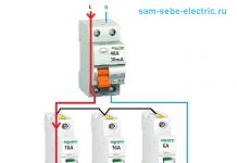
The scheme is simple and one of the most common. For an RCD, it is important not to make a mistake about where the neutral (N), incoming (1) and outgoing (2) conductors are located. . Then, machines for individual lines can be reconnected to its output.
Three-phase input
In a three-phase circuit, single-phase consumers can also be protected. The inputs of the “zero” and “ground” buses are combined. The electricity meter is installed between the main circuit breaker and the RCD.

Three-phase RCD connection diagram
The load current of the RCD must be protected from overloads. To do this, it is selected one step higher than that of the machine next to it.
From the point of view of using RCDs, one should distinguish between the working neutral wire N and the protective earth zero PE. Through the first, current flows during normal operation, and through the second only when an accident (leakage) occurs.
Incorrect connection often occurs, causing the protection to constantly trip. Moreover, this alone can cause a failure in the work of the entire group.
RCD in apartments
A two-pole RCD installation is selected for the apartment. You also need to determine the electric current values that characterize it:
- cutoff exceeds the maximum current consumption by 25%;
- rated current for which the device is designed (indicated in the characteristics and must exceed the cut-off current);
- differential protection response indicator.
A device with alternating current is selected for the apartment. If there is a large amount of equipment, unreasonable tripping of the RCD is possible. To prevent this from happening, increase the threshold current value to the maximum acceptable and safe for humans (30 mA).
The device is mounted in the panel on DIN rails or through special holes. It is marked with phase and neutral wires. The entrance is from above, and the exit is from below.
Single-level protection with one device at the entrance allows you to completely stop the supply of electricity to the apartment. It is also installed on individual devices, for example, on a washing machine or electric stove.
If you place the RCD in separate areas, the circuit will turn out to be cumbersome, but the shutdowns will be autonomous. For a separate device, the connection is made in front of the machine.
Common connection errors.
- Weaving neutral wires into a knot. As a result, unexpected operations occur.
- Making homemade grounding is not according to the rules (resistance above 4 ohms).
- The connection of “zero” to “ground” leads to periodic power outages.
RCD in a private house
Private homeowners use a large number of devices that require an individual RCD. These include a washing machine, an electric heating boiler, a sauna stove, machine tools, a welding transformer and other equipment. The longer the list, the greater the likelihood of its elements failing.
For an individual home, a TT system with a solid neutral and connecting the conductive parts of the devices to an independent ground is suitable. It is most often made modular-pin.
The RCD is placed in the switchboard. Four-pole and two-pole devices are used depending on which consumers are connected: single-phase or three-phase. The cascade principle remains, but the circuit is more complex. The input is made three-phase, and there are many more consumers than in an apartment. The general rules for connecting protection are the same as in an apartment.
In a private home, they are often used that combine the functions of an RCD circuit breaker. Its advantages are as follows:
- less space in the shield;
- ease of installation;
- trip due to leakage, short circuit or overload;
- the price is lower than that of two separate devices whose functions it combines.
Similarly: with and without grounding, using a selective or non-selective method. The phase and neutral of the circuit are also connected to them, which is not allowed to be combined with grounding, since the currents in these conductors are fundamentally different.

Differential machines in a private house
Disadvantage: if it fails, you have to buy the automatic device again, which is equivalent to replacing two devices at once. Also, not everyone knows how to use such complex equipment and prefers to make do with automatic machines. But at the same time, connecting grounding to the housings of devices without RCDs or automatic circuit breakers is unacceptable. Conventional machines do not provide the network shutdown speed necessary for human safety.
The rules for using RCDs are also relevant for differential automatic machines.
RCD connection. Video
This video will tell you in detail about the connection diagram of the residual current device.
The operation of the residual current device is based on limiting the time of electric current flowing through the human body (by quickly disconnecting) in case of accidental contact with live parts of electrical installations. Some schemes for its connection also provide for disconnecting the network immediately when a leakage current occurs through the ground wire.
When properly installed and maintained, RCDs ensure the safe use of electrical appliances in the apartment and house. Electromechanical devices that meet the requirements of GOST are reliable.
An RCD is necessary in modern housing, since its cost is immeasurably lower than that of modern household and electronic equipment, which can fail, but the most important thing is to ensure electrical safety.
RCD with rated current 40 A
RCBO with overcurrent protection OptiDin VD63 with rated current up to 63A
Residual current device(abbr. RCD; more precise name: residual current device controlled by differential (residual) current, abbr. RCD-D) or residual current switch (VDT) or protective switching device (ZOU) - mechanical switching device or a set of elements that, when the differential current reaches (exceeds) a given value under certain operating conditions, should cause the contacts to open. May consist of various individual elements designed to detect, measure (compare with a given value) differential current and fault and opening electrical circuit (disconnector).
The main task of the RCD is protection person from electric shock and from the occurrence fire caused by current leakage through worn wire insulation and poor-quality connections.
Combination devices that combine RCDs and overcurrent protection device, such devices are called RCD-D with built-in overcurrent protection, or just diffautomatic. Often differential automatic devices are equipped with a special indication that allows you to determine for what reason the operation occurred (from overcurrent or differential current).
Purpose
RCDs are intended for
- Protecting people from electric shock when indirect touch(person touching open conductive non-current-carrying parts of an electrical installation that become energized in the event of insulation damage), as well as when direct touch(person touching live parts of an electrical installation that are energized). This function is provided by RCDs of appropriate sensitivity (cut-off current no more than 30 mA).
- Preventing fires when leakage currents occur on the housing or on land.
Goals and operating principle
The operating principle of the RCD is based on measuring the balance of currents between the current-carrying conductors included in it using a differential current transformer. If the current balance is disturbed, the RCD immediately opens all contact groups included in it, thus disconnecting the faulty load.
The RCD measures the algebraic sum of currents flowing through the controlled conductors (two for a single-phase RCD, four for a three-phase, etc.): in the normal state, the current “flowing” through one conductors must be equal to the current “flowing out” through the others, then there is a sum of currents passing through the RCD equal to zero (more precisely, the sum should not exceed the permissible value). If the amount exceeds the permissible value, then this means that part of the current passes in addition to the RCD, that is, the controlled electrical circuit is faulty - there is a leak in it.
Detection of leakage currents using an RCD is an additional protective measure, and not a replacement for overcurrent protection using fuses, since the RCD does not react in any way to faults if they are not accompanied by current leakage (for example, short circuit between phase and neutral conductors).
RCDs with a residual current of about 300 mA or more are sometimes used to protect large sections of electrical networks (for example, in computer centers), where a low threshold would lead to false alarms. Such low-sensitivity RCDs perform a fire-fighting function and are not effective protection against electric shock.
Example
Internal structure of the RCD connected to the power cord break
The photograph shows the internal structure of one type of RCD. This RCD is intended for installation into a power cord break; its rated current is 13 A, with a differential tripping current of 30 mA. This device is:
- RCD with auxiliary power supply;
- performing automatic shutdown when the auxiliary source fails.
This means that the RCD can only be turned on if there is supply voltage; if the voltage fails, it will automatically turn off (this behavior increases the safety of the device).
The phase and neutral conductors from the power source are connected to contacts (1), the RCD load is connected to contacts (2). The protective grounding conductor (PE conductor) is not connected to the RCD in any way.
When pressing the button (3) contacts(4) (as well as another contact hidden behind node (5)) close, and the RCD passes current. Solenoid(5) keeps the contacts closed after the button is released.
Reel (6) on toroidal The core is the secondary winding of the differential current transformer, which surrounds the phase and neutral conductors. The conductors pass through the torus but have no electrical contact with the coil. In the normal state, the current flowing through the phase conductor is exactly equal to the current flowing through the neutral conductor, but these currents are opposite in direction. Thus, the currents mutually compensate each other in the coil of the differential current transformer EMF absent.
Any leakage of current from the protected circuit to grounded conductors (for example, a person standing on a wet floor touching a phase conductor) leads to an imbalance in the current transformer: “more current flows through the phase conductor” than returns through the zero conductor (part of the current flows through human body, that is, in addition to the transformer). An unbalanced current in the primary winding of a current transformer leads to the appearance of an emf in the secondary winding. This EMF is immediately recorded by the tracking device (7), which turns off the power to the solenoid (5). The disconnected solenoid no longer holds the contacts (4) in the closed state, and they open under the action of the spring force, de-energizing the faulty load.
The device is designed in such a way that shutdown occurs in a split second, which significantly reduces the severity of the consequences of electric shock.
The test button (8) allows you to check the functionality of the device by passing a small current through the orange test lead (9). The test wire passes through the core of the current transformer, so the current in the test wire is equivalent to an imbalance of the current-carrying conductors, that is, the RCD should turn off when the test button is pressed. If the RCD does not turn off, it means it is faulty and must be replaced.
Application
In Russia, the use of RCDs became mandatory with the adoption of the 7th edition Rules for electrical installations(PUE). Typically, in the case of household electrical wiring, one or more RCDs are installed on DIN rail in the electrical panel.
Many manufacturers of household devices that can be used in damp areas (for example, hair dryers), provide for such devices a built-in RCD. In a number of countries, such built-in RCDs are mandatory.
Conditions for triggering the RCD:
- Direct human contact with live parts and contact with the ground.
- Damage to the main insulation and contact of live parts with a grounded body.
- Replacement of neutral and grounding conductors.
- Replacement of phase and neutral conductors and human contact with live parts and its simultaneous contact with the “ground”.
- Breakage of the neutral conductor before (and after the RCD) and a person touching live or live parts and simultaneously making contact with the ground.
Examination
It is recommended to check the performance of the RCD monthly. The easiest way to check is to press the " test”, which is usually located on the body of the RCD (as a rule, the “test” button has an image of a large letter “T”). The button test can be performed by the user, meaning that qualified personnel are not required. If the RCD is working properly and is connected to the electrical network, then when you press the “test” button it should immediately work (that is, turn off the load). If after pressing the button the load remains energized, then the RCD is faulty and must be replaced.
The push button test is not a complete test of the RCD. It may be triggered by a button, but will not pass a full laboratory test, including measurement of the residual current and trip time.
In addition, pressing the button checks the RCD itself, but not whether it is connected correctly. Therefore, a more reliable test is to simulate a leak directly in the circuit, which is the load of the RCD. It is advisable to perform such a test at least once for each RCD after its installation. Unlike pressing a button, a test leak must be carried out only qualified personnel.
Restrictions
An RCD can significantly improve the safety of electrical installations, but it cannot completely eliminate the risk of electric shock or fire. The RCD does not respond to emergency situations unless they are accompanied by a leak from the protected circuit. In particular, the RCD does not respond to short circuits between phases and neutral.
The RCD will also not work if a person is under voltage, but no leakage has occurred, for example, when a finger touches both the phase and neutral conductors at the same time. Provide electrical protection from such touches is impossible, since it is impossible to distinguish the flow of current through the human body from the normal flow of current in the load. In such cases, only mechanical protective measures are effective ( insulation, non-conductive casings, etc.), as well as disconnecting the electrical installation before servicing it.
Some types of RCD ( RCD-D with auxiliary power supply, see ) need power, which they receive from the protected circuit. Therefore, a potentially dangerous situation is when in the protected circuit above the RCD the neutral conductor is disconnected, but the phase conductor remains energized. In this case, the RCD will be unable to disconnect the circuit, since the potential difference in the protected circuit is insufficient for the operation of the RCD. So called electromechanical RCDs do not require power and are therefore free from this disadvantage.
Story
In the early 1970s, most RCDs were produced in housings of the type circuit breakers. Since the early 1980s, in the USA, most household RCDs were already built into sockets. In Russia, RCDs began to be used much later - approximately from 1994-1995. And until now, RCDs are mainly used for installation in the electrical panel on DIN rail, but built-in RCDs have not yet become widespread.
RCD classification
By mode of action
- RCD without auxiliary power supply
- RCD-D with auxiliary power supply:
- performing automatic shutdown in case of failure of the auxiliary source with and without time delay:
- automatically restarting when the auxiliary source is restored
- not automatically restarting when the auxiliary source is restored
- not producing automatic shutdown in case of failure of the auxiliary source:
- capable of shutting down if a dangerous situation arises after failure of an auxiliary source
- unable to shut down in the event of a hazardous situation following failure of an auxiliary source
- performing automatic shutdown in case of failure of the auxiliary source with and without time delay:
By installation method
- stationary with installation of fixed electrical wiring
- portable with installation by flexible wires with extension cords
By number of poles
- single-pole two-wire
- bipolar
- two-pole three-wire
- three-pole
- three-pole four-wire
- four-pole
By type of protection against overcurrent and overcurrent
- without built-in overcurrent protection
- with built-in overcurrent protection
- with built-in overload protection
- with built-in short circuit protection
For loss of sensitivity in case of double grounding of the neutral working conductor
Under consideration
If possible, regulate the disconnecting differential current
- unregulated
- adjustable:
- with discrete regulation
- with smooth regulation
In terms of resistance to impulse voltage
- allowing the possibility of switching off during impulse voltage
- impulse voltage resistant
According to operating conditions
- RCD-D type AC - a protective shutdown device that responds to an alternating sinusoidal differential current that occurs suddenly or slowly increases;
- RCD-D type A - a protective shutdown device that responds to alternating sinusoidal differential current and pulsating direct differential current, occurring suddenly or slowly increasing;
- RCD-D type B. The RCD responds to alternating, direct and rectified differential currents.
- RCD-D type S - selective (with a shutdown time delay), this may be necessary where an automatic transfer switch is used.
- RCD-D type G - the same as S, but with a shorter time delay.
The use of type A RCDs is advisable in certain cases, for example, in circuits containing consumers with thyristor control without an isolating transformer. Type B RCDs are used in industrial electrical installations with mixed power supply - alternating, rectified and direct currents.
RCD characteristics
Characteristics common to all RCDs
³=== Only for RCD-D without built-in short circuit protection ===
- Type of short circuit protection
- Rated conditional short-circuit current Inc - the effective value of the expected current specified by the manufacturer, which the RCD-D, protected by the short-circuit protection device, can withstand under given operating conditions without irreversible changes that impair its functionality
- Rated conditional differential current at short circuit I Δc - the value of the expected differential current specified by the manufacturer, which the RCD, protected by the short-circuit protection device, can withstand under given operating conditions without irreversible changes that impair its functionality
see also
Notes
Links
- GOST R 50807-95 (2003) Protective devices controlled by differential (residual) current. General requirements and test methods (IEC 755-83).
- SP 31-110-2003 “Design and installation of electrical installations of residential and public buildings”
- HTML version of the educational and reference manual "UZO". Publishing house "Energoservice", 2003.


