Based on basic savings, you begin to think about how not to turn on the lights around the clock. Lighting in different rooms especially on different floors. Whether they have their own house or an apartment, everyone has the same problem. In the recent past, lights were on everywhere without turning off. How can you make a connection that will solve this problem? And there is a way out. To prevent the light from being constantly on, it is possible to control it from different places.
It is possible to turn the lamps on and off from different places. And this opportunity exists thanks to pass-through switches. They may be called “duplicate” or “reversible”. But this is all one type of equipment. They differ from ordinary ones in the large number of contacts. Therefore, connecting these switches is more complicated. And so we deal with the pass-through switch.
How does a pass-through switch work?
- 1 How does a pass-through switch work?
- 2 Connection diagram for a switch from two places
- 3 Three-point scheme
- 4 Two-key switch: connection diagram
If we talk about the visible difference, then this is the only thing: a barely noticeable arrow on the up and down key.
It looks like a pass-through one-key switch, there are double arrows

The circuit of a pass-through switch is not so complicated: in simple switches there are only two contacts, in pass-through switches (also redundant) there are three contacts, two of which are common. There are always two or more such switches in the connection diagram; they are assembled using common wires.
The difference is in the number of contacts
A simple principle: changing the position of the key switches the input to one of the outputs. Pass-through switches have only two operating positions:
- input to output 1;
- input to output 2.
There are simply no other provisions. This is why it all works. Because the contact switches from one position to another, it is more correct to call them "switches". Therefore, the pass-through switch is the same device.
Even if the arrows on the keys are not visible, we disassemble the contact part. Standard products indicate a connection diagram that allows you to understand what type of equipment you have in your hands. All more or less self-respecting manufacturers have this scheme. Many Chinese do not have this scheme.

Rear changeover switch
If there is no diagram, look at the contacts (copper clips in the holes): you will find three contacts. Very often, a separate contact, especially with inexpensive manufacturers, is the input. They are often confused. To determine the general contact, you just need to ring at different positions of the key. This must be done in any case, otherwise it may not work, and the switch itself may burn out.
Using a tester or multimeter, we determine which of these three is common.
After watching this video you will understand how to find the input (common contact) for a pass-through switch.
Connection diagram for a pass-through switch from two places
Such a connection will be needed on the stairs of a two-story house or in a long corridor. You can also use it even in the bedroom - turn off the overhead lights at the entrance and near the bed (remember how many times you suffered with this)

Connection diagram for a pass-through switch with 2 places
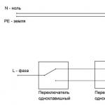
Zero and ground (if any) are supplied directly to the lamp. The phase is connected to the output of the first switch, the input of the second is connected to the free wire of the lamp, the outputs of the two switches are connected to each other.
Looking at the diagram, it is immediately clear how the pass-through switch works. The lamp in the picture is in the on position. When you press a key on any of the devices, the circuit breaks. Also, in the off position, by pressing the key, we will close the circuit through one of the jumpers and the lamp will light up. pass-through switch connection diagram
For clarity, here are a few examples.

Wiring on the pass-through switch
Speaking of the room, the wiring should be done as shown in the photo below. According to the rules, they should be located at a distance of 15 cm from the ceiling. They can be laid both in corrugations and boxes; wires are inserted into installation boxes. For the convenience of possible wire replacement. According to the latest standards, all connections are made only using contactors in junction boxes. When using twists, they need to be soldered and well insulated.
We connect the return wire of the lamp to the output of the second switch. White indicates the wires connecting the outputs of both devices.

Wiring around the premises
How to connect everything in the terminal box is described in the video.
Connection diagram for pass-through switch to 3 points
To adjust the switch from three places, add a cross (cross) switch to two switches. It differs from those previously described by the presence of two inputs and two outputs. He switches a couple of contacts at once. See the figure for the connection diagram. If you understand what was above, understanding this one will not be difficult. pass-through switch connection diagram

Three-point lamp control circuit
- Zero (and ground, if any) is connected directly to the lamp.
- The phase is connected to the input of one of the pass-through switches (with three inputs).
- The input of the second is fed to the free wire of the lamp.
- The two outputs of one three-contact device are connected to the input of a crossover switch (with four inputs).
- The two outputs of the second three-contact device are connected to the second pair of switch contacts with four inputs.
The same diagram, but from a different perspective - where to connect the wires on the housings.

Where to connect the wires
And this is approximately how to distribute it around the room.

Wiring when controlling the lamp from three places
If a circuit with four, five or more points is needed, then the only difference is the number of cross switches (for four inputs/outputs). There are always two switches (with three inputs/outputs) - at the beginning and at the end of the circuit. All others are cross switches.

connecting pass-through switches to 5 points
If you remove one crossbar, you get a four-point control scheme. Add more - there will already be a circuit for 6 control points. pass-through switch connection diagram
Also watch this video.
Connection diagram for pass-through switch two keyboards
To control two or more lamps (or a group of lamps) from several places, it is necessary to use two-key pass-through switches. The two rocker switches have six contacts. You can find common wires using the same principle as in a conventional device of this type, only the number of wires will increase.

The switching circuit of a 2-key pass-through switch is distinguished by a large number of wires: the phase is supplied to both inputs of the first switch, just as from the two inputs of the second it must go to two lamps (or two groups of lamps, if we are talking about a multi-arm chandelier).

The principle of connecting two-key pass-through switches
To organize control of two or more light sources from three or more points, you will have to install two cross switches at each point: there are simply no two-key switches. In this case, one pair of contacts is placed on one crossbar, the second on the other. And later they are connected to each other. The outputs of both crossbars are connected to the two-key transition switch, which is the last one in the circuit.
Information to note: ,
Pass-through switch - the very name of this type of electrical device already shows their true purpose. The devices belong to the family of standard household switches, familiar to all residential property owners.
Actually, the design of the devices externally resembles the traditional design. The only difference is how to connect the pass-through switch, the contact group diagram of which is slightly different.
Let's figure out together what rules should be followed when connecting a pass-through switch, and what actions should be abandoned.
The convenience and practicality of this type of device are obvious. Electrical networks equipped with such communicators are operated more efficiently, since in the end there are actual energy savings.
For example, to cross a long corridor, the lighting is turned on at the entrance and turned off at the exit. This function is implemented by just two devices mounted at different ends of the corridor.
This is what it is - a pass-through switch, which is actively increasing the degree of competition in relation to its relative - a conventional device. This seemingly slightly modified model gives the user more benefits
If we compare the design with a conventional on/off device, the difference is noted in the number of working contacts of the devices. The design of a simple switch provides only the closing/opening of two contacts.
The wiring of the pass-through switch involves the creation of three working lines, of which one is common, and the other two are changeover lines. This makes it possible to control a section of an electrical circuit from various points.
All the subtleties of selection and types of pass-through switches are described.
Operating principle of the single-key model
Actually, the principle of the function looks simple and clear. The changeover contacts existing in the structure in the first position close one segment of the circuit and open the other, and in the second position of the changeover contacts the circuit is inverted.

The principle of operation of the device in a schematic view: L – phase line of the electrical household network; N – electrical zero line of the household network; C – general communication contact; P – changeover communication contacts; 1 – one device; 2 – second device
On the body of each branded switch there is always a schematic diagram of its connection. For example, the user has a single-key device at his disposal. It is necessary to include it in a simple control circuit for one lamp.
Detailed instructions for installing a single-key switch are presented in.
If we refer to the installation diagram of a single-key pass-through switch, which is contained on its body, the user’s actions boil down to the following:
- The first (C) contact is connected to a common line.
- Changeover segments are connected to the second (P) and third (P) contacts.
- Install two devices at previously designated points.
The changeover contacts (P) of the two switches, identical in number, are connected to one another by conductors. The first (common - Common) contacts of the two devices are connected - one with the phase wire, the second with the “zero” wire through the lamp lamp.
The operation of the circuit is tested as follows:
- The mounted section of the circuit is provided with voltage.
- Switch the key of the first switch to the “On” mode.
- The lighting lamp lights up.
- Follow to the location of the second device.
- Change the current position of the key of the second device.
- The lighting lamp turns off.
Now, if you do all the operations in reverse order, the effect of the lighting system will be similar. This confirms the normal operation of the circuit.
How to do the actual installation?
Before you begin installing an apartment (or other) walk-through switch, it is recommended to draw a wiring diagram, something like this:

An example of creating a diagram for installing a system of feed-through switches: N – neutral wire of the network; L – phase wire of the network; RK – distribution box; PV1 – first device; PV2 – second device; 1,2,3 – contact groups
The current supply to the section of the circuit with pass-through switches is usually carried out through a standard distribution box. Thus, the first step of installation is selecting the optimal location for the junction box, installing it and supplying electrical wiring. The three-core cable (phase-zero-ground) is brought into the box.
In addition to installing the distribution box, the natural need remains to prepare niches for mounting the chassis of walk-through switches. The most convenient places are also chosen for them. Typically, devices are mounted next to the frames of pass-through doors.

One of the possible options for installing communication with two devices is one at each of the passage doors. This option is quite applicable for classic projects of residential and office buildings
Having completed the preparatory installation procedures, proceed to connecting the separated conductor lines. The first is connected to any of the switches, to its 1 output (phase conductor).
Next, the conductors are connected between the changeover contacts. The last line to be connected is the zero line to the remaining free first contact of the second switch. All that remains is to supply voltage to the assembled circuit (turn on the circuit breaker) and test the assembly for correct operation.
Cross designs
There is a modification of the devices - cross switches. Structurally, they are devices with four contact switching. Their main purpose is to help design switching circuits for lamps and other devices from three or more control points.

Circuitry with a cross-action model: 1 – regular switch; 2 – cross-action switch; 3 – regular switch; 4 – distribution box; 5 – lamp lamp; N – network zero conductor; L – phase conductor
Meanwhile, to implement such circuits involving cross models in the structure, it is necessary to use conventional pass-through switches. The circuit implementation involves the inclusion of cross modifications in series between a pair of conventional pass-through switches. The crossover model has a pair of input terminals and a pair of output terminals.
Read about the intricacies of installing crossover switches.
Products are produced for external (surface) installation and devices for use in hidden wiring networks. There is a wide choice of load capacities, and the variety of colors and designs also does not limit user needs.
Circuit solutions for practical operation
The most commonly used circuits for connecting pass-through devices are, as a rule, circuits for one-, two-, devices. The single-key option was discussed above.
Therefore, let’s see what the step-by-step instructions for connecting a two-key device look like.
- It is necessary to schematically outline the installation of the system.
- Carry out work on installing the switchgear and socket boxes.
- Install the required number of light groups.
- Lay out the network taking into account the supply of phase, neutral, and grounding conductors.
- Connect the separated conductors according to the drawn diagram.
Attention should be paid not only to purely electrical installation work, but also to technical work. For example, it is recommended to pay great attention to the installation of socket boxes.
These elements must be securely fastened to the wall so that in the future they provide no less reliable fastening of the devices.
There is a three-point communication system, which is based on creating a system that allows you to control a light group of three points separated at a distance. The elemental base consists of three devices, of which two are and one is cross-device.

A widespread version of the three-point circuit: N – electrical zero; L – electrical phase; PV1 – first two-key switch; PV2 – second two-key switch; PV3 – crossover switch
A kind of connection instruction in this case looks something like this:
- A wiring and connection diagram is created.
- Work is underway to install the distribution box and socket boxes.
- Three-core electrical cables are laid in the amount of 4 pieces.
- Electrical installation is carried out - connection according to the diagram.
This option for creating a communication power network looks somewhat complicated. As is clear even from laying the cables, you will have to deal with a total of 12 conductors. Regular pass-through switches require 6 wires, while a crossover switch requires 8 wires.
A phase line is connected to the common terminal of any of the two-key switches. The line of the light group is connected to the common line of the second two-key switch. The remaining conductors are connected according to the contact numbers according to the schematic diagram.
Touch switch models
In addition to keyboard and lever modifications, there are touch-sensitive models on the market. In essence, the functions of the devices are the same, but the principle of operation, as well as the design, are somewhat different.

The modern modification is a touch model, which has a more convenient operating principle. In addition, this type of household communicators has an increased service life due to the absence of mechanics in the design
There are two types of touch switches:
- Direct sensors.
- Touch sensors with dimmers.
The first ones work on direct, clear contact through a brief touch of the fingertip to the glass panel of the device. That is, in this option only the on/off function works. The second design option (dimmer) provides switching on and off with smooth control of the brightness of the lamps.
To work with these devices, the same finger touch is required, followed by holding the fingertip on the glass until the required brightness of the lamp is achieved.

Rear view of the touch device, where the connection terminals are located: COM – synchronizing connector for working in pairs with other devices; L – contact for the network phase; L1 – first output channel; L2 – second output channel
The circuitry of sensor devices differs from devices of other designs in that it contains one common (phase) terminal (L), two changeover terminals (L1, L2) and one “COM” terminal.
The "COM" contact is used for communication between switches when building complex circuits. For example, with control of several lighting zones from three or more points. In this case, a load power of no more than 1 kW is allowed per light zone.

The classic version of circuit wiring with one sensor device: N – electrical zero; L – electrical phase; L1 – load of the first channel; L2 – load of the second channel
A simple organization of a control system with one sensor device is performed as follows:
- The phase line is connected to the “L” terminal.
- Line "L1" forms one lighting zone.
- Line "L2" forms the second lighting zone.
If a group of devices is used, the phase contacts of the devices (L) are connected in parallel, plus the “COM” terminals are connected to each other. All other terminals are connected as standard depending on the number of switched light zones.
In order for touch devices to function correctly, they must be programmed. Essentially, we are talking about synchronizing all switches in a group. Programming is performed in the following sequence:
- Touch the sensor for 5 seconds. until a beep sounds (or the LED blinks).
- After the beep, release the touch and move on to the next device.
- Touching the sensor of the second device.
- If the LED on the front panel responds with short flashes, success.
These are the seriously modified electrical components that the familiar electrical switches look like. Now these are no longer just switches for electric lamps screwed into chandelier sockets.
These devices can be successfully used to control other objects. For example, performing work on raising and lowering curtains on the windows of an apartment.
If you have had to install a pass-through switch yourself in your own home, please share your experience with our readers. Tell us how you implemented this task in practice. Leave your comments in the block below. There you can ask questions about the topic of the article, and we will try to answer them promptly.
Very often you have to turn lighting on and off from several points. For example, in long corridors, on stairs, in basements. You can ensure independent switching on and off of lighting fixtures from 2 remote points using 2 pass-through switches, and in combination with a cross switch, you can control lighting from 3 or more points. The main thing is the correct connection diagram.
Pass-through switches
Before you understand what a cross switch is used for, you need to understand how it works.
The neutral wire is connected directly to the lighting device, the phase wire is connected through two switches connected to each other by a two-core wire.
If contacts 1 and 3 are closed on switches PV1 and PV2, then the circuit is closed and current flows through the light bulb. To open the circuit, you need to press the key of any switch, for example, PV1, in which case contacts 1 and 2 will be closed. By pressing the key of switch PV2, the circuit will close. Thus, the lamp can be turned on and off independently from two remote locations.
What is a cross switch used for?
If you need to provide lighting control from three points, 2-way switches will not be enough. A crossover switch should be inserted into the gap in the two-core wire connecting the pass-through switches, as shown in the diagram.
The contacts of all the switches in the diagram are closed so that current flows through the wires shown in red. If you press a key on any of the 3 switches, the circuit will open. It is enough to press a key on any other switch, and the circuit is closed. Current will flow through the wires shown in blue.
If you need to control lighting from 4 points, you need to use the following scheme:
You can control the lighting using cotton switches or motion sensors. But they have disadvantages:
- high price;
- these types of switches quickly fail;
- clap switches may be triggered by extraneous sounds but not triggered by clap;
- switches with motion sensors can respond to the movement of animals and birds.
You may find the instructions useful, which describe the technology for connecting a single-key switch:.
Types of switches
According to their design, cross switches are divided into 2 types: key and rotary.
Keyboards
Switches of this type are most often used.
Key switches, or more correctly called switches, break one circuit and close another. Conventional switches only open or close one circuit. Externally, they are practically the same. They can only be distinguished from the back by the number of contacts:
- a regular single-key has 2 contacts;
- at the passer -3;
- the cross one has 4.
Differences between regular, pass-through and cross single-key switches (photo gallery)
A single-key pass-through switch has 3 contacts  A conventional single-key switch has 2 contacts. A single-key cross switch has 4 contacts.
Key switches can have 1, 2 or 3 keys. Multi-key switches are designed to control multiple circuits independently.
Rotary cross
Switches of this type are installed less frequently than keyboard switches. They are usually used in warehouses and industrial premises, for street lighting, and as interior decoration in apartments. The contact groups in them are closed and opened by turning the lever.
Appearance of rotary switches (photo gallery)
 Used in warehouses
  Used as interior decoration
  Used in residential areas Controls 2 circuits
  Used in rooms with high humidity and for street lighting
Overhead and built-in
According to the installation method, switches are divided into 2 types: overhead and built-in.
Built-in switches are installed during the construction or renovation stage in boxes installed in niches. The wires are laid in grooves or attached to the walls. Typically, this method is used before plastering walls or covering them with plasterboard or other materials.
Surface-mounted switches and their associated wires are attached to the wall. In this case, there is no need to scratch the walls and knock out recesses for the boxes. They are usually installed in this way during cosmetic renovations. Overhead switches create certain inconveniences: dust accumulates on them, people cling to them while moving. In some cases, owners, on the contrary, prefer this type of switches for interior design.
Characteristics of cross switches
The electrical products market has a wide selection of switches and switches from domestic and foreign manufacturers. The difference in price between different manufacturers is significant, but the dimensions and technical characteristics are similar.
Main characteristics
Models with housings that protect against moisture and steam are more expensive.
Pay attention to the article with instructions for connecting a three-key switch:.
Installation of pass-through and cross switches
The best option for developing an electrical circuit and installing it is during the construction of a house or during its major renovation. It is necessary to take into account all rooms in which it may be necessary to independently turn on and off lighting from 3 remote points. These are long corridors, basements with several entrances and exits, flights of stairs. Yard buildings and street lighting should also be taken into account.
For those who are planning to install lighting themselves, but do not have the skills, experts advise first assembling a temporary lighting circuit by connecting 2 pass-through switches with short wires and connecting a light bulb. You should remember which contacts the wires were connected to. After making sure that the circuit is assembled correctly, the switches need to be disconnected.
Sequencing
Lighting installation is carried out in the following order:

How do you know if the lights are off if the power suddenly goes out?
During installation, it is advisable to install all switches so that when they are off, their keys are in the same positions, for example, “up”.
For interior work, any two-core insulated wire, the cross-section of which corresponds to the expected load, is suitable. For street lighting, double insulated wire is used.
Practice has shown that it is cheaper and more practical to control lighting in long corridors, on flights of stairs, and in basements using walk-through and crossover switches.
Do you want the light to turn on when you clap? Then read our article, which describes the technology for connecting such a system: .
Video: how to connect a pass-through switch
All stages of assembling a temporary circuit with 2-pass switches can be viewed in more detail in this video.
Video: how to connect a cross switch
Please note: in the video the crossover switch is called an "intermediate" switch.
A well-thought-out and well-executed lighting control scheme using pass-through and crossover switches will make living conditions in the house more comfortable and eliminate many problems. There is no need to skimp on quality, but the described lighting control scheme from several independent points will be much cheaper than using cotton switches or switches with motion sensors. At the same time, it is more reliable and durable.
Switching light sources according to the principle “approach, turn on, pass, turn off” is one of the options for the efficient use of electrical energy. The functionality of such a control system is provided by the same traditional devices - switches, but structurally somewhat modernized.
Switching modernization allows you to connect a pass-through switch from two or three places in order to control the light source from each individual point. Agree, this solution is especially convenient for long rooms, for example, a corridor.
We suggest you understand the principles of connecting a pass-through switch to two and three control points. The article provides working diagrams for organizing light groups, and also describes the features of the implementation of switching projects.
The logic of saving energy spent on lighting devices or others is explained by simple user actions.
If a lighting device is needed, electricity is supplied to it by simply closing the switch contact. Otherwise, the opposite action is performed.
Light source switch - interpreted in electrical slang - a pass-through switch. Provides a fundamentally new approach in terms of operation of electrical sections of networks intended for the installation of lighting devices (+)
However, let’s assume that the premises (residential or other purposes) are passable. Then the user will turn on the lights at the entrance, but when leaving the room through another door, he will no longer be able to de-energize the circuit. There is irrational use of electricity.
But the situation is easy to improve. And the option of connecting from two places in the room for a pass-through mode scheme will help to do this.

Long corridors of premises for different purposes are potential objects for the installation of control systems for light sources from different places. It is during the operation of such premises that the pressing issue of energy saving is raised.
For example, there is a room with a functional purpose - a corridor. It is required to control the general group of lamps for this room from two points - at the first (passage) door and at the second (passage) door.
Switching light from two places
The lighting of the project corridor consists of two light groups, so in this case it is logical to use two two-key switches for control.
Accordingly, in addition to them you will need:
- two socket boxes;
- one ;
- three-core cable.
The meterage of electrical conductors should be calculated after drawing up the diagram and layout of the wiring. It is recommended to purchase a cable with a small margin.
The control circuit for two light groups through two-key pass-through switches looks something like this:

Control circuit for two separate light groups through two-key devices: N, L – classic electrical network; RK – distribution box for cable routing; L1, L2 – separate light groups; P – jumper; PV1, PV2 – two-key pass-through switches (+)
The phase conductor is supplied to the two-key device PV1. This switch, configured with two keys, has two common contact terminals and four changeover contact terminals.
On the first device, the common terminals are connected together and the phase conductor is connected to them. Terminal 1 of the changeover contact PV1 is connected by wire to terminal 1 of the changeover contact PV2. Accordingly, contact 2 of PV1 will be connected to terminal 2 of PV2, terminal 3 of PV1 to terminal 3 of PV2, and terminal 4 of PV1 to terminal 4 of PV2.
There are two more terminals left on the second pass-through switch. Both are common, and they are connected according to the principle: each to one light group (L1 and L2) of the lighting system. Already from the light groups, the outgoing conductors close the circuit to the zero bus of the electrical network.
However, this is only one of the possible circuit solutions. So, if one light group is used, you can organize the circuit using single-key switches.
Wiring using single-key pass-through switches looks more economical in terms of material consumption. Less wire is required here, since the number of connecting lines is reduced by almost half, compared to the previous solution.
But, at the same time, the functionality of the lighting system itself is limited.

Circuit design for one light group using single-key switches: L, N, PE – classic power distribution on three lines; RK – junction box; L1 – light group; PV1, PV2 – single-key switches (+)
However, for devices in residential premises, this option can be used most often.
What is required for a control system based on single-key switches?
The answer is obvious:
- single-key switches (2 pcs.);
- socket boxes (2 pcs.);
- distribution box (1 pc.);
- three-core (measurement according to calculation).
The requirements for the system design are standard. Before work begins, a diagram is drawn up. The necessary accessories, materials, and fasteners are purchased. The distribution box is also in the designated places.

An example of a wiring device for a residential premises from the category of standard projects. Two single-key switches are used. The solution is made taking into account the wiring of the cable with the grounding conductor (PE). This option matches the diagram shown above
Then the cable is routed and connections are made between the pass-through switches from two places with the light source through the junction box.
The phase conductor is connected to the common terminal PV2, and the common terminal PV1 is connected to one contact of the light group. The second contact of the light group is connected to the zero bus, and the changeover contacts of both switches are switched with each other, observing identical numbering (1 from 1, 2 from 2).
Three control point solution
The organization of pass-through switching systems is largely determined by the area of the premises (length) and the number of passages (doors). Therefore, the use of circuits with pass-through switches from three or more control positions is not excluded.
The construction of such schemes is usually carried out with the participation of the so-called.
This is the same switch, but in terms of circuit design it is made with five contact terminals, two of which are short-circuited with a jumper. The switching group of such a switch contains four contact pads.

A widely used circuit design for residential buildings: N, L – household network; RK – distribution box; L1 – light group; PV1, PV2 – pass-through switches; PRK – cross commutator (+)
The line cross-switching device is an additional element of the circuit, which also involves the installation of two pass-through switches.
Simple single-key instruments are used.
The operating principle of the three-seater scheme is as follows:
- A phase is connected to the “common” terminal PV1.
- The 1st and 2nd contacts of the crossover switch are connected from the changeover contact terminals.
- From the 3rd and 4th terminals of the crossover switch, connection to the 1st and 2nd terminals of the PV2 changeover contacts.
- The common terminal “common” PV2 is connected to one terminal of the light group.
- The second terminal of the light group is connected to the electrical zero.
Such solutions involving simple single-key devices are recommended for use in rooms where the number of inputs/outputs is equal to the number of control places.

Implementation of the circuit design according to Fig. 6 in a “natural” form. This is roughly what a completed installation looks like indoors, where a control system from three places is needed
For example, creating a similar circuit for the conditions of passing a long corridor, with 1 entrance and 1 exit, with switching in the central zone, is clearly impractical. Obviously, it makes no sense to turn off the lights when a person has only passed the first half of the corridor. Meanwhile, you can find similar recommendations from “professional” electricians on the Internet.
Schemes with control from more than three places
The number of control places is, in principle, unlimited. Another question is how complex such decisions are. The more devices are involved in the implementation of the control system, the more complex the construction scheme becomes.
The number of switched lines and contact terminals is increasing. Accordingly, costs for components and installation increase. However, projects with 4-5 control points are used quite actively. For example, this project:

Circuit design for projects that require an increase in the number of control locations of more than three. In this case, the option is for four control points (+)
It uses a pair of single-key simple pass-through switches and a pair of switches with a reversible switching function. The diagram shows only one light group. Meanwhile, it is possible to connect additional light groups.
Additional light groups
Additional light sources (light groups) can be connected via free terminals and act as light sources for intermediate transition zones. That is, in the same long corridors it becomes possible to use the circuit for a larger number of control positions.

Five-point control circuit for the light switching system: L1 – light group; N, L – network; On 1, On 2 – pass-through switches; On 3, On 4, On 5 – reversible switches (+)
In this case, light groups should be divided into action zones - entrance, intermediate, exit. With this solution, it is already possible to walk through a long corridor halfway, turn off the lights on the completed half and turn on the lights on the remaining half.
Multi-element schemes, of course, are of little use for the private residential sector, since projects of this kind rarely have long corridors or large rooms with several doors. But for the commercial sphere or production environment, solutions of this kind are in demand.
Principles of control system design
In general, there are no installation features for installing pass-through switches. All installation work is carried out in a standard manner, in accordance with the rules for installing conventional switching devices.

Classic installation detail for wiring inside walls. The socket box is installed (tightly walled up). An electrical cable is routed inside the socket box. A control device is connected (two-key)
If the budget allows, it is advisable to equip each individual device with a distribution box. Then you need to purchase small boxes according to the number of mounted switches. But the option with one RC is also not excluded.
The selection factors here are directly related to specific installation conditions. Typically, switches are installed “flush” with the wall surface - internal wiring diagram.
Meanwhile, the implementation of projects for private (country) properties often involves the installation of “overhead” (surface) installation schemes, despite the fact that this approach is considered obsolete.
For the first case, socket boxes will be required for installation. For the second - overhead plates. These accessories are necessary to securely mount switches in wall panel niches or directly on walls.

The cable is connected strictly according to the diagram indicated on the back of the device. The circuit layout of a single-key switch is simple. However, mismatch of conductors with incorrect wiring can result in failure of the device.
The electrical conductor, as a rule, is three-core cables, where two cores are needed to power the system, and the third is used to form a protective grounding loop.
Household lamps can be used without an “earth” if the body is non-metallic. Industrial lamps must have a grounding bus.
Of course, regardless of its purpose, domestic or industrial, the installed network is always connected through additional protection -. This device must be calculated based on power and cutoff current in relation to the built-through light control system.
Features of connecting a two-key pass-through switch are described in this article
The appearance and implementation of devices of this kind in electrical networks may not be so significant, but it still affected the ease of use. Moreover, solutions based on pass-through switches actually lead to energy savings.
Meanwhile, the improvement of devices does not stop. New developments appear periodically, for example, similar to touch switches.
Do you have anything to add or have questions about connecting the pass-through switch? You can leave comments on the publication, participate in discussions and share your own experience in arranging an electrical network. The contact form is located in the lower block.
Content:The feasibility of using walk-through switches is determined by the individual layout of the room with lamps that require adjustment from different points. Thus, additional convenience and comfort are provided. In such cases, a circuit for connecting a pass-through switch from three places is quite often used. If necessary, it is possible to use more points.
Using three-switch circuits
Using a light control system with three switches makes it possible to turn the lighting on and off from any convenient location. Walk-through switches have proven themselves well on flights of stairs, in large rooms, entrances, as well as in the yard or on a personal plot.
In long corridors, several switches are installed, at the beginning, in the middle or at the end. The same scheme is used when there are several entrances to different rooms. That is, at the beginning of the corridor the light can be turned on, and in the middle or at the end it can be turned off. In order for the lighting device to be turned on and off from three different points in the room, it is necessary to use a connection diagram with three pass-through switches.
Elements and components of the connection diagram
This circuit includes a junction box, lighting fixtures, switches and wires. Not only conventional incandescent lamps are used as lighting sources, but also various types of LED and energy-saving lamps. The switches used in the circuit are divided into pass-through and cross-type. In turn, pass-through switches can be changeover, redundant or ladder switches. Their installation takes much longer compared to.

The classic scheme for connecting a pass-through switch from three places requires the use of two and one cross. The appearance of the duplicating devices is almost the same as that of a single-key device. In any position of the keys of such a switch, the connection of the electrical circuit is not interrupted, only the contacts are switched. The switching mechanism in pass-through switches is located in the center of the contacts.
Devices can be one- or two-key. In the second case, two devices are combined into one with six contacts. Circuits often use single-key light switches that do not differ from each other. Each of them is equipped with three contacts. The first device has a phase wire connected to one contact, and intermediate wires to the other two. The third switch, on the contrary, has an intermediate wire connected to one contact, and the output phase lines to the other two.

The switch installed in the middle performs the function of a cross switch. It has four contacts, from which two wires go to each changeover switch No. 1 and No. 3. If the intermediate electrical wire is shorted on any of the changeover devices, the light will turn on. When the state of the key changes, the circuit breaks and the light goes out. If there is a need to increase the number of light control points, it is enough to add cross switches in the required number to the existing circuit.
To correctly install the control system, certain recommendations must be followed. If the room already has an electrical network, then separate open or closed networks must be connected to the backup switches. In the second case, it is necessary in the walls. You may need special tools and plaster to secure the corrugated pipe. New lines are laid using a three- or four-core cable.
How to connect a pass-through switch from 3 places


