
The leading position among the most efficient sources of artificial light today is occupied by LEDs. This is largely a merit of quality food sources for them. When working in conjunction with a properly selected driver, the LED will retain a stable brightness of light for a long time, and the life of the LED will be very, very long, measured in tens of thousands of hours.
Thus, a properly selected driver for LEDs is the key to a long and reliable operation of the light source. And in this article we will try to reveal the topic of how to choose the right driver for an LED, what to look for, and what they are like.
A driver for LEDs is called a stabilized constant voltage or constant current power supply. In general, initially, an LED driver is, but today even constant voltage sources for LEDs are called LED drivers. That is, we can say that the main condition is the stable characteristics of the DC power supply.
An electronic device (essentially a stabilized pulse converter) is selected for the required load, whether it be a set of individual LEDs assembled in a serial chain, or a parallel set of such chains, or there may be a tape or even one powerful LED.
A stabilized constant voltage power supply is well suited for LED strips, or for powering a set of several high-power LEDs connected one at a time in parallel - that is, when the rated voltage of the LED load is exactly known, and you just need to select a power supply for the rated voltage at the corresponding maximum power .

Usually this does not cause problems, for example: 10 LEDs at 12 volts, 10 watts each, will require a 100 watt 12 volt power supply, rated for a maximum current of 8.3 amperes. It remains to adjust the output voltage with the help of a regulating resistor on the side, and you're done.
For more complex LED assemblies, especially when several LEDs are connected in series, you need not just a power supply with a stabilized output voltage, but a full-fledged LED driver - an electronic device with a stabilized output current. Here, the current is the main parameter, and the supply voltage of the LED assembly can automatically vary within certain limits.
For an even glow of the LED assembly, it is necessary to ensure the rated current through all the crystals, however, the voltage drop across the crystals may differ for different LEDs (since the CVCs of each of the LEDs in the assembly differ slightly), so the voltage will not be the same on each LED, but the current should be the same.

LED drivers are produced mainly for power supply from a 220 volt network or from a 12 volt vehicle on-board network. The driver output parameters are specified as a voltage range and current rating.
For example, a driver with an output of 40-50 volts, 600 mA will allow you to connect four 12-volt LEDs with a power of 5-7 watts in series. Approximately 12 volts will drop on each LED, the current through the series circuit will be exactly 600 mA, while the voltage of 48 volts falls into the operating range of the driver.
A constant current LED driver is a universal power supply for LED assemblies, and its efficiency is quite high, and here's why.
The power of the LED assembly is an important criterion, but what determines this load power? If the current were not stabilized, then a significant part of the power would be dissipated in the equalizing resistors of the assembly, that is, the efficiency would be low. But with a driver that has current stabilization, equalizing resistors are not needed, so the efficiency of the light source will turn out to be very high as a result.
Drivers from different manufacturers differ in output power, protection class and applied element base. As a rule, it is based on, with current output stabilization and with protection against short circuit and overload.
Powered by AC 220 volts or DC with a voltage of 12 volts. The simplest compact drivers with low voltage supply can be performed on one universal chip, but their reliability, due to simplification, is lower. Nevertheless, such solutions are popular in autotuning.

When choosing a driver for LEDs, it should be understood that the use of resistors does not save you from interference, as well as the use of simplified circuits with quenching capacitors. Any voltage surges pass through resistors and capacitors, and the non-linear IV characteristic of the LED will necessarily be reflected in the form of a current surge through the crystal, and this is harmful to the semiconductor. Linear stabilizers are also not the best option in terms of immunity from interference, besides, the effectiveness of such solutions is lower.
It is best if the exact number, power, and switching scheme of the LEDs are known in advance, and all the LEDs in the assembly will be of the same model and from the same batch. Then choose a driver.
The range of input voltages, output voltages, and rated current must be indicated on the case. Based on these parameters, a driver is selected. Pay attention to the protection class of the case.
For research tasks, for example, unpackaged LED drivers are suitable; such models are widely represented on the market today. If it is necessary to place the product in a housing, the housing can be manufactured by the user himself.
Andrey Povny
I have posted several reviews of LEDs, it's time to write what you can feed them.
The review involves three items of detail (links and prices are present), but they are all needed for one purpose, to make a driver for the LED.
I immediately apologize for the title photo, it stubbornly tries to scale in its own way, I couldn’t fix it, it’s more correct on the seller’s page.
Everyone knows that LEDs are powered by current, preferably stabilized, so that the brightness does not change when the voltage changes. For this purpose, a driver is used, in fact a current stabilizer.
You can limit the current with simple microcircuits such as LM317 and current stabilizers specially designed for this (there is an overview of one such part on the muse), but they usually emit quite a lot of heat, since they have low efficiency. But the advantage of LEDs is just in high efficiency.
More interesting are switching regulators current, they are more complicated, but have a much greater efficiency, especially if the supply voltage is very different from the voltage on the LED.
Yes, many will say that it is easier to buy such a driver in China and not bother, I agree.
But it's always nicer to do something with your own hands. Actually, I decided so, ordering components for the driver.
Maybe I'm reinventing the wheel. But the review includes components that are useful for many other tasks, and perhaps many will find information about what they sell and what we actually get useful.
Let's start with the microchip. This is a fairly well known PT4115 LED fan. description -
The microcircuit has an output for brightness control. The input, as I understand it, can be controlled by PWM or by changing the voltage. The input is quite high-resistance, since when you touch this pin, the LED starts to flicker at a frequency of 100 Hz.
The cost of a lot of 10 pieces is $2.
After ordering the chip, the seller unsubscribed that the package would be without a track and asked if it would suit me, I decided that $ 2 was not the money to worry about and gave the go-ahead.
After some time, I found an envelope in the mailbox.
Inside was a bag with the chips I needed.

I checked one microcircuit, connecting it with a hinged mount, wrote to the seller that everything was in order, confirmed receipt and began to wait for the rest of the details.
After that came the throttles.
The cost of a lot of 20 pieces is 7.36 dollars.
They have already been brought to my house (as well as the next order).
They were packed in a cardboard box, although such a measure seems unnecessary to me.
By the way, we have such chokes are much more expensive, and I bought them not only for this.
Actual chokes, Inductance 68 μH, current 1.6 or 1.8 Amperes (not indicated by the seller, therefore approximately), dimensions 12x12x7mm.

Measurement of the inductance showed a deviation within the error.

Similarly to the first case, I confirmed the order, left a good review.
Well, at the end came the Schottky diodes. Since the thing is necessary in the household, I ordered a hundred of them.
Wanted more, but didn't risk it.
The price of a lot of 100 pieces is $5.26. They are also more expensive for us.

The diodes are marked as SS34, in fact they are smaller, in size and characteristics they fully correspond to the SS24 diodes.
I measured the voltage drop across the diode at a current of 1 Ampere and he arranged for me.

On this part of the purchases on Aliexpress ended.
In principle, this could have ended the review, but it would be wrong to buy parts and not try them out in practice. Therefore, it was naturally decided to bring the matter to some kind of logical conclusion.
When I was on the market, along the way I bought smd resistors 1206 with a resistance of 1 Ohm for a current sensor.
At first I thought about buying low-resistance resistors right away, like in a datasheet for a microcircuit, but they come out much more expensive and if you want to tune to different currents, then you need to buy several ratings, in general, it’s inconvenient, and I sometimes use 1 Ohm resistors.
in the end it turned out that 1 such resistor approximately corresponds to a current of 0.1 amperes, two in parallel 0.2 amperes, etc. smd resistors and capacitors are conveniently soldered to each other, so you can easily select the required current.
I had capacitors for the input power filter and textolite trimmings, but nothing else is required.
Well, in general, I began to reinvent my bicycle driver. I threw a quick scarf in Sprint, the scheme was from the datasheet, so I didn’t have to invent anything.
I picked up a piece of textolite to make 5 boards at once (I plan to convert 5 halogen lamps to LEDs).
Some pictures of the process and diagram


Transferred to textolite.

I etched it, drilled holes, cut it into separate scarves, tinned the tracks and washed it from the flux residues.

Collected all the necessary components

The output turned out to be such a handkerchief, it is larger than those sold by the Chinese, but it has a more powerful choke and two parallel diodes, respectively, lower losses and greater reliability, and the dimensions were completely uncritical for me.

After that, naturally I wanted to check (where without it).
Tested with these LEDs -
Along the way, it turned out that the microcircuit stabilizes the current normally, but all the same, with a one and a half times increase in the input voltage, the output current, although slightly, changes.
But I sin a little on the fact that there may be a large error due to the pulsating current (the output current was measured in series with the LED).
It was possible, of course, to measure the current using a resistor and an oscilloscope, but I considered this unnecessary, since the transition from the linear mode to the current limit was clearly visible, and the subsequent transition to the stabilization mode in the PWM stabilization mode.
The shunt rating was 1/6=0.166 Ohm.
With these parameters at the input, the output was a current of 0.7 Ampere.

With such a current at the output was 0.65 Ampere

Before the threshold voltage of the transition to the PWM stabilization mode, I received the maximum current -

With a smooth increase in the supply voltage, the input current first grew smoothly, after switching to stabilization mode and further increase, it began to gradually fall, which indicates the operation of PWM stabilization.
By the way, with a very smooth increase in the supply voltage, a transition is noticeable, the brightness of the LED first gradually increases, after the transition it abruptly decreases by 10 percent, after which (with a further increase in the input voltage) it no longer changes.
Apparently, this is how the microcircuit works out the inclusion of PWM stabilization.
Heating at a current of 600mA is practically not felt, there is nothing to measure without contact, and contact measurement will introduce a large error.
I tried to give 1 Ampere to the output, the heating certainly increased, but not much. and only the microcircuit had heating. In general, I was satisfied.
Ask why you didn’t buy ready-made on the same Ali?
-Details will be useful in other crafts.
- I wanted to stretch my arms a little.
- The cost of all components turned out to be about $ 1 per 1 board.
-I decided to test not the finished device, but the details, since they are used not only in drivers.
-At the output, I received a more reliable device than China's stores offer.
I really hope this review is helpful.
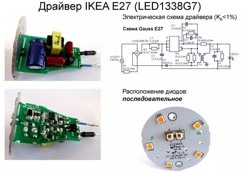
I plan to buy +121 Add to favorites Liked the review +129 +282Today, probably, not a single apartment or a private house not without LED lighting. And street lighting is gradually changing to economical and durable LED-elements. But looking at today's topic of conversation, one asks - what does the driver have to do with it (from the English “driver” is translated that way)? This is the first question that comes to the mind of a person who is ignorant of the LED lighting device. In fact, without such a device, light diodes do not work with a voltage of 220 V. Today we will figure out what function the LED driver performs, how to connect this device and whether it is possible to make it yourself.
Read in the article:
Why do we need drivers for LEDs and what is it
The answer to the question, what is an LED driver, is quite simple. This is a device that stabilizes the voltage and gives it the characteristics that are needed for the operation of LED elements. To make it clearer, let's draw an analogy with a ballast fluorescent lamp, which also cannot work without additional equipment. The only difference is that the driver has compact size and fits in the body of the light fixture. In fact, it can be called stabilizing starting device or frequency converter.

Where are stabilizing devices for LED elements used?
LED drivers for LEDs are used in various fields:
- street lights;
- household lighting lamps;
- LED strips and various lighting;
- office lamps with the form of fluorescent lamps.
Even car daytime running lights require the installation of such a device, but everything is much simpler here, you can get by with one resistor. And although the driver for led strip(for example) differs in characteristics from the voltage regulator of a light bulb, they perform the same function.

Working Principle of 220V LED Lamp Driver Circuit
The principle of operation of the device is to maintain a given current at the output voltage (regardless of its value). This is the difference from the stabilizing power supply, which is responsible for the voltage.

Considering the circuit, we see that the current, passing through the resistances, stabilizes, and the capacitor gives it the desired frequency. Then the rectifying diode bridge comes into play. We get a stabilized direct current on the LEDs, which is again limited by resistors.
Noteworthy Driver Features
The characteristics of the converters required in a particular case are determined based on the parameters of the LED consumers. The main ones are:
- Driver Rated Power- this parameter must exceed the total power consumed by the light diodes that will be in its circuit.
- Output voltage- depends on the magnitude of the voltage drop on each of the light diodes.
- Rated current, which depends on the brightness of the glow and the power consumption of the element.

It's important to know! The voltage drop across an LED depends on its color. For example, if you can connect 16 red LEDs to a 12 V power supply, then maximum amount green will be 9.
Separation of LED drivers by device type
Converters can be divided into two types - linear and pulse. Both types are applicable to light diodes, but the differences between them are noticeable both in cost and in technical characteristics.

Linear converters are characterized by simple design and low cost. But such drivers have a significant drawback - the ability to connect only low-power light elements. Part of the energy is spent on heat generation, which contributes to a decrease in the coefficient of performance (COP).
Pulse converters are based on the principle of pulse-width modulation (PWM) and during their operation, the magnitude of the output currents is determined by such a parameter as the duty cycle. This means that there is no change in the pulse frequency, but the duty cycle can vary by values from 10 to 80%. Such drivers allow you to extend the life of light diodes, but they have one drawback. During their operation, it is possible to induce electromagnetic interference. Let's try to figure out what it threatens a person on simple example.

A person living in an apartment or house has a pacemaker installed. At the same time, in small room a chandelier was installed with many devices operating on pulsed ice drivers for. In this case, the pacemaker may begin to malfunction. Of course, this is exaggerated and to create such strong interference, you need a lot of lamps that are less than a meter away from the pacemaker, but there is still a risk.

How to choose a driver for an LED: some nuances
Before purchasing a converter, calculate the power consumed by the LEDs. The rated power of the device must exceed this figure by 25 ÷ 30%. Also, the stabilizer must match the output voltage.
If hidden placement is planned, it is better to choose a converter without a case - the cost will be lower with the same technical characteristics.

Important! Drivers Chinese made usually do not meet the declared characteristics. Don't skimp on purchasing a "made in" converter. It is better to give preference to the Russian manufacturer.
How to connect LED elements to the converter: methods and diagrams
LEDs are connected to the driver in two ways - in series or in parallel. For example, let's take 6 LED emitters with a voltage drop of 2 V. When connected in series, you need a driver for 12 V and 300 mA. In this case, the glow will be even for all elements.

By connecting the emitters in parallel in a group of 3, we get the opportunity to use a 6 V converter, but already at 600 mA. The problem is that due to the uneven voltage drop, one line will glow brighter than the other.
We calculate the characteristics of the converter for LEDs
For an accurate calculation, we first determine the power consumption of the LEDs. After the issue is resolved with the connection diagram - will it be parallel or serial. This will depend output voltage and rated power of the required converter. This is all the work that needs to be done. Now, in an electrical engineering store or on an online resource, we select a driver according to the calculated indicators.

Good to know! When purchasing a converter, ask the seller for a certificate of conformity for the product. If it is missing, it is better to refrain from buying.
What is a dimmable LED driver
Dimmable is a driver for an LED lamp that supports changing the input current parameters and is able to change the output depending on this. This is achieved by changing the intensity of the glow of LED emitters. An example would be a remote controlled LED strip controller. If desired, it becomes possible to "dim" the lighting in the room, to give rest to the eyes. It is also appropriate if a child is sleeping in the room.

Dimming is performed from the remote control, or from a standard mechanical stepless switch.
Chinese converters - what is special about them
Chinese friends are famous for their ability to fake equipment so that it becomes impossible to use. The same can be said for drivers. When purchasing a Chinese device, be prepared for overstated specifications, low quality and a quick failure of the converter. If you are going to build the first LED-lamp in your life, practice and gain skills in radio electronics, such products are indispensable due to their low cost and ease of execution.

What affects the service life of converters
The reasons for the failure of the converter are:
- Sudden power surges in the network.
- High humidity if the device does not meet the degree of protection.
- Temperature fluctuations.
- Insufficient ventilation.
- Increased dustiness.
- Incorrect calculation of consumer power.

Any of these causes can be prevented or corrected. This means that it is in the power of the home master to extend the life of the stabilizing device.
PT4115 LED driver circuit with dimmer
We are talking about a Chinese manufacturer, which is an exception to the rule. A microcircuit, on the basis of which it is possible to assemble the simplest converter just by its production. The PT4115 microprocessor has good performance and gaining popularity in Russia.

Related article:
If the lighting is LED and conventional regulators are not suitable, then they are installed, which are slightly different structurally and technically. Today we will figure out what they are, how to choose and even make such a device yourself.
The figure shows the simplest circuit driver PT4115 for LEDs, which can be assembled by a novice home master without experience with radio electronics. Interesting in the chip is an additional output (DIM) that allows you to connect a dimmer (dimmer).
How to make a DIY LED driver
Any novice master can assemble an LED lamp driver circuit. But this will require accuracy and patience. From the first time, the stabilizing device may not work. To make it clearer to the reader how the work is done, we offer several simple schemes.


As you can see, there is nothing complicated in driver circuits for LEDs from a 220 V network. Let's try to consider step by step all the stages of work.
DIY step-by-step instructions for making a driver for LEDs
| Photo example | Action to take |
|---|---|
 | To work, we need a regular power supply for the phone. It makes everything quick and easy. |
 | After disassembling the charger in our hands, we already have an almost complete driver for three one-watt LEDs, but it needs to be slightly modified. |
 | We solder a 5 kOhm limiting resistor, which is located near the output channel. It is he who does not charger apply too much voltage to the cell phone. |
 | Instead of a limiting resistor, we solder a tuning resistor by setting the same 5 kOhm on it. Subsequently, add voltage to the required. |
 | 3 LEDs of 1 W each are soldered to the output channel, connected in series, which will give us a total of 3 W. |
 | We find the input contacts and unsolder from printed circuit board. We no longer need them... |
 | ... and in their place we solder the power cord, through which 220 V will be supplied. |
 | If desired, you can put a 1 Ohm resistor in the gap, set all indicators with an ammeter. In this case, the attenuation range of the LEDs will be wider. |
 | After complete assembly, we check the performance. The output voltage is 5 V, the LEDs are not yet lit. |
 | By turning the knob on the resistor, we see how the LED elements begin to “flare up”. |
Be careful. From such a converter, you can get a discharge not only of 220 V (from the power cord), but also a shock of about 450 V, which is rather unpleasant (tested on yourself).
Very important! Before you check the LED driver for performance and connect it to a power source, you should once again visually check the correctness of the assembled circuit. Defeat electric shock life-threatening, and a flash from a short circuit can cause damage to the eyes.
Current converters for light diodes: where to buy and what is the cost
Such devices are purchased in electrical stores or on the Internet resources. The second option is more cost effective. In addition, many manufacturers offer free shipping. Consider some models with an input voltage of 220 V with technical specifications and value as of December 2017.
| A photo | Model | Protection class, IP | Output voltage, V | Power, W | Cost, rub. |
|---|---|---|---|---|---|
| DFT-I-40- LD64 | 20 | 60-130 | 45 | 400 | |
| ZF-AC LD49 | 40 | 40-70 | 54 | 450 | |
| XS0812-12W PS12 | 20 | 24-44 | 12 | 200 | |
| PS100 (open) | 20 | 30-36 | 100 | 1100 | |
| PF4050A PS50 | 65 | 27-36 | 50 | 500 | |
| PF100W LD100 | 65 | 23-36 | 100 | 1000 |
Looking at the prices, we can say that the independent manufacture of a current converter is more suitable for those for whom it is only a hobby. You can buy such a device quite inexpensively.

Summarize
When choosing a current converter for LED lamps, you should carefully calculate everything. Any error can lead to a decrease in the service life of the purchased device. Despite the low cost of the stabilizer, it is rather unpleasant to constantly throw money away. Only in this case the driver will serve its due period. And when self-manufacturing follow the rules of electrical safety and be careful and attentive when assembling the circuit.
We hope that the information provided today was useful to our reader. You can ask any questions in the discussion - we will definitely answer them. Write, ask, share your experience with other readers.
And finally, a short video on today's topic:
The widespread use of LEDs led to the mass production of power supplies for them. Such blocks are called drivers. Their main feature is that they are able to stably maintain a given current at the output. In other words, a driver for LEDs is a current source for powering them.
Purpose
Since the LED is a semiconductor element, the key characteristic that determines the brightness of their glow is not voltage, but current. In order for them to be guaranteed to work for the declared number of hours, a driver is needed - it stabilizes the current flowing through the LED circuit. It is possible to use low-power light-emitting diodes without a driver, in which case a resistor plays its role.
Application
Drivers are used both when powering an LED from a 220V network, and from sources of constant voltage 9-36 V. The former are used when lighting rooms with LED lamps and ribbons, the latter are more common in cars, bicycle headlights, portable lamps, etc.
Principle of operation
As already mentioned, the driver is a current source. Its differences from a voltage source are illustrated below.
The voltage source creates a certain voltage at its output, ideally independent of the load.
For example, if you connect a 40 ohm resistor to a 12 V source, a current of 300 mA will flow through it.
If you connect two resistors in parallel, the total current will be already 600 mA at the same voltage.

The driver maintains a given current at its output. The voltage may change.
We also connect a 40 ohm resistor to the 300 mA driver.

The driver will create a 12V drop across the resistor.
If you connect two resistors in parallel, the current will still be 300 mA, and the voltage will drop to 6 V:

Thus, the ideal driver is able to provide the load with the rated current regardless of the voltage drop. That is, an LED with a voltage drop of 2 V and a current of 300 mA will burn as brightly as an LED with a voltage of 3 V and a current of 300 mA.
Main characteristics
When selecting, you need to take into account three main parameters: output voltage, current and power consumed by the load.
The output voltage of the driver depends on several factors:
- voltage drop across the LED;
- number of LEDs;
- connection method.
The current at the output of the driver is determined by the characteristics of the LEDs and depends on the following parameters:
- LED power;
- brightness.
The power of LEDs affects the current they draw, which can vary depending on the required brightness. The driver must provide them with this current.
The load power depends on:
- power of each LED;
- their quantity;
- colors.
In general, the power consumption can be calculated as

where Pled is the power of the LED,
N is the number of connected LEDs.
The maximum power of the driver should not be less.
It is worth considering that for stable operation of the driver and to prevent its failure, a power margin of at least 20-30% should be provided. That is, the following relation must hold:

where Pmax is the maximum power of the driver.
In addition to the power and number of LEDs, the load power also depends on their color. LEDs of different colors have different voltage drops at the same current. For example, the XP-E red LED has a voltage drop of 1.9-2.4V at 350mA. The average power consumed by it in this way is about 750 mW.
The green XP-E has a 3.3-3.9V drop at the same current and will average about 1.25W. That is, a driver designed for 10 watts can power either 12-13 red LEDs or 7-8 green ones.
How to choose a driver for LEDs. Ways to connect LED
Let's say there are 6 LEDs with a voltage drop of 2V and a current of 300mA. You can connect them in various ways, and in each case you will need a driver with certain parameters:

It is unacceptable to connect 3 or more LEDs in parallel in this way, since in this case too much current can flow through them, as a result of which they will quickly fail.
Please note that in all cases the driver power is 3.6 W and does not depend on the way the load is connected.
Thus, it is more expedient to choose a driver for LEDs already at the stage of purchasing the latter, having previously determined the connection scheme. If you first purchase the LEDs themselves, and then select a driver for them, this can be a difficult task, since the likelihood that you will find exactly the power source that can provide the operation of this particular number of LEDs, included in a particular scheme, is small.
Kinds
In general, LED drivers can be divided into two categories: linear and switching.
The linear output is a current generator. It provides stabilization of the output current with an unstable input voltage; moreover, the adjustment occurs smoothly, without creating high-frequency electromagnetic interference. They are simple and cheap, but their low efficiency (less than 80%) limits their scope to low-power LEDs and strips.

Pulse are devices that create a series of high-frequency current pulses at the output.

Typically, they operate on the principle of pulse-width modulation (PWM), that is, the average value of the output current is determined by the ratio of the width of the pulses to their period (this value is called the duty cycle).
![]()
The diagram above shows how a PWM driver works: the pulse frequency remains constant, but the duty cycle varies from 10% to 80%. This leads to a change in the average value of the current I cp at the output.
Such drivers are widely used due to their compactness and high efficiency (about 95%). The main disadvantage is the higher level of electromagnetic interference compared to linear ones.
220V LED Driver
For inclusion in the 220 V network, both linear and pulsed ones are produced. There are drivers with galvanic isolation from the network and without it. The main advantages of the former are high efficiency, reliability and safety.
Without galvanic isolation, they are usually cheaper, but less reliable and require care when connecting, since there is a possibility of electric shock.
Chinese drivers
The demand for LED drivers contributes to their mass production in China. These devices are impulse sources current, usually 350-700 mA, often without a case.

Chinese driver for 3w led
Their main advantages are low price and galvanic isolation. The disadvantages are the following:
- low reliability due to the use of cheap circuit solutions;
- lack of protection against overheating and fluctuations in the network;
- high level radio interference;
- high output ripple;
- fragility.
Life time
Typically, the life of the driver is less than that of the optical part - manufacturers give a guarantee of 30,000 hours of operation. This is due to factors such as:
- instability of mains voltage;
- temperature fluctuations;
- humidity level;
- driver load.
The weakest link LED driver are smoothing capacitors that tend to evaporate the electrolyte, especially in conditions of high humidity and unstable supply voltage. As a result, the level of ripple at the output of the driver increases, which negatively affects the operation of the LEDs.
Also, the incomplete loading of the driver affects the service life. That is, if it is designed for 150 W, and operates at a load of 70 W, half of its power returns to the network, causing it to overload. This causes frequent power failures. We recommend reading about.
Driver circuits (microcircuits) for LEDs
Many manufacturers produce specialized microcircuits drivers. Let's consider some of them.
ON Semiconductor UC3845 is a switching driver with output current up to 1A. The driver circuit for the 10w LED on this chip is shown below.

Supertex HV9910 is a very common switching driver IC. The output current does not exceed 10 mA, has no galvanic isolation.
A simple current driver on this chip is shown below.

Texas Instruments UCC28810. Network impulse driver, has the ability to organize galvanic isolation. Output current up to 750 mA.

Another chip from this company, a driver for powering high-power LEDs LM3404HV, is described in this video:
The device works on the principle of a Buck Converter resonant converter, that is, the function of maintaining the required current is partially assigned to the resonant circuit in the form of a coil L1 and a Schottky diode D1 (a typical diagram is shown below). It is also possible to set the switching frequency by selecting the resistor R ON .

The Maxim MAX16800 is a linear chip that operates at low voltages, so you can build a 12 volt driver on it. The output current is up to 350 mA, so it can be used as a power driver for a powerful LED, flashlight, etc. There is a possibility of dimming. A typical scheme and structure are presented below.

Conclusion
LEDs are much more power hungry than other light sources. For example, exceeding the current by 20% for a fluorescent lamp will not lead to a serious deterioration in performance, while for LEDs, the service life will be reduced several times. Therefore, you should be especially careful when choosing a driver for LEDs.
How to check the LED driver for performance and compliance with the declared power parameters can be found in the video:
Checking the LED spotlight matrix:
Types of drivers by device type
There are two types of LED drivers:
- Linear. A typical linear driver circuit is based on a P-channel transistor. Such a device is best used if the input voltage is unstable. It provides smoother current stabilization, is reliable in operation and has an affordable price. Despite these disadvantages, this driver has not been widely used. It is characterized by low efficiency, it generates a lot of heat during operation and cannot be used to connect powerful ones.
- Pulse. The operating principle is based on pulse-width modulation. The current conversion efficiency of such devices reaches 95%. They are small in size, emit little heat, protect from the negative effects of external factors. Their use has a positive effect on the duration of the LED-lighting.

Important! Pulse drivers have a fairly high level of electromagnetic interference. In theory, people using pacemakers may feel discomfort from being in a room lit by such devices. However, as practice has shown, in order for the driver's magnetic field to affect the pacemaker, it is necessary for a person to be at a distance of less than a meter from a high-powered LED spotlight.
Dimmable LED Drivers
Modern LED drivers in most cases include fixtures that adjust brightness. lighting fixtures. The application allows you to adjust the comfortable level of lighting in the room. In addition, this allows you to save the working life of LED-illuminators.

The dimming device can be placed between the power supply and the LED illuminator. Such devices directly control the energy supplied to the LEDs. As a rule, these are pulse devices based on PWM regulation. They regulate the amount of current flowing. In some cases, when using low-cost LED sources, negative effects such as flickering can be observed.
The second type of dimmer converter controls the power supply. In principle, their influence is both PWM regulation and control of the current flowing through the device. In this case, not only a change in brightness, but also the color of the LEDs can be observed. For example, white LEDs with this adjustment can emit yellowish light when reduced in intensity and bright blue exaggeration.
Do-it-yourself driver circuit for LEDs based on PT4115 with a dimmer

The use of PT4115 in the driver circuit allows the use of several types of power supplies: with a voltage of 12÷240 V and 12÷18 V in the second case, a diode bridge with a capacitor installed at the output must be introduced into the general LED driver circuit with PT4115.


Making a driver for LEDs with your own hands
| Illustration | Description of works |
 | To facilitate the work, you can take the old one from the mobile phone. |
 | The device actually is and incorporates almost all the necessary radio components for connecting several one-watt LEDs. |
 | It is necessary to remove a limiting resistor from the circuit, which protects the phone from applying excessive voltage. In this case, this is a 5 kΩ resistor located at the output channel. |
 | In place of the static resistor, you need to solder a tuning resistor. At first, it is advisable to set it to the same 5 kOhm. During the tuning process, the voltage can be raised to the desired level. |
 | 3 LEDs are connected to the output channel in serial connection. Provided that they have a power of 1 W, the total power consumption at the output will be 3 W. |


