
Sliding gates without automatics are an almost ideal fencing solution for summer cottages or country house. The design is very convenient, easy to operate, reliable and durable. If you have a desire and little knowledge of plumbing, then it will not be difficult for you to make them yourself. To do this, you will need a diagram (drawing), according to which you will independently build a structure.
IMPORTANT! Since the gate will not be automatic, the lock will hang from the inside and therefore it should be near the gate so that you can enter and open (close) the gate manually. Or you can build a gate directly into the gate.
We have prepared for you a short step by step instructions about how to make simple sliding gates from metal profiles and corrugated board.
photo of sliding gates from corrugated board
The main advantages of these gates are:
- external aesthetic appearance. They look modern and quite stylish;
- significantly save the space of the territory, so they can be installed even in small courtyards;
- maximum guarantee of safety;
- good strength and load-bearing characteristics;
- saves time cleaning the yard from snow and debris.
Device and principle of operation
Mechanical sliding (sliding) gates, they are also called retractable, there are console and rail. We will consider a cantilever version of the gate without automation, which is most suitable for a private house or cottage. The driving mechanism in them is a rigid console(guide beam). It is welded from below to the metal profile frame.
The guide beam moves along the rollers of the carriages. Each carriage is equipped with eight rollers.
The main elements of sliding gates
- frame;
- Carrying trolley;
- Carrier beam;
- Plateau with rollers from side swings;
- end roller;
- End roller trap.
We will sheathe the frame with corrugated board - the gate will be light and durable.

Drafting and installation
- Before starting the installation process of the fence, it is important to draw up a correct drawing with a detailed marking of the length, width, height, not forgetting the gaps and the rollback distance. The correct assembly of the structure and the choice of the necessary components will depend on all these parameters. Be sure to consider the width of the opening for the arrival of the car, as well as the width of the street;
- After developing the drawing, it is necessary to prepare the very place where the structure will be installed - it must be carefully leveled and cleaned of contaminants;
- First, support pillars are installed, they can be made of various materials: concrete, brick, steel, etc. The pole is fixed at a depth of at least a meter.
Channel preparation
On a 200 mm wide channel, according to the exact dimensions of your drawing, weld the bolts that will hold the carriages. Before welding, check 7 times that you have marked the places for the bolts correctly.
Foundation

foundation
- The laying process begins with the excavation of a U-shaped trench, approximately 1600-1700 mm deep. (see figure above). Then fill the bottom of the pit with sand 15 cm and tamp;
- Cut the reinforcement into elements (the length of each is 1500 mm) and weld it to the channel shelves. Then start the process of laying the channel with reinforcement in the trench, not forgetting to align the channel at the end with the water level;
- Fasten the carriages to the bolts with nuts;
- Place the guide beam on the carriages and check its progress;
- If everything is smooth (check the level again), then you can fill the trench with concrete and wait about 2 weeks.
The foundation is ready.

frame
We cook the frame (frame) for the gate from a metal profile with a section of 40x40 mm. Do not forget to strengthen it with additional profiles. Choose the reinforcement option yourself, given that a heavily reinforced frame will be heavier, which will affect the further service life and can significantly increase the wear rate of components. From below, we weld the guide beam to the frame with a longitudinal cut down.
Accessories
guide beam

Mechanism

accessories
- Carriages;
- Lower roller catcher;
- Video clip;
- plug;
- Upper catcher;
- Guiding device.
Gate fastening
We install the frame on the carriages, after placing a brick or bar under the left side (where is the entrance). Be sure to ask the help of a partner to hold the frame.

gate frame installation
Then we adjust and fasten the guide device to the top of the post:

guiding device
After the frame is installed, you will need to fasten it to it with self-tapping screws. Try to keep it straight so that the edges are secure and don't stick out from behind the frame.
Catchers
The next step is the installation of a metal rack for traps. It can be screwed to the fence with anchor bolts, then traps can be fixed to it. Remember to insert the roller into the left side of the guide beam and the plug into the right side.

installation of traps
That's it, your sliding gates are ready! You can weld the handle and hinges for the lock from the inside. And do not forget to make an emphasis, for example, from rubber, so that when the gate opens, it stops them at the end of the path. It is also desirable to make a canopy so that precipitation does not fall on the mechanism. Good luck with your creative work!
Reading time ≈ 4 minutes
High-quality gates that roll to the side when opening and closing help save free space on the site. They are easy to install, durable and attractive. appearance. Decking attached to the frame will protect the site from gusts of wind and significantly reduce noise on the territory. Installing retractable is not difficult, you just need to properly prepare and take into account the basic requirements of the manufacturer.
Blueprints


Simple design sliding gate assumes the presence of supporting elements supporting the supporting and feigned frames. The depth of the foundation for a gate with a leaf of 3.5 m (distance between foundations 3.175 m) should not be less than 1.5 m below the ground and 2.5 cm above the ground. A larger foundation must be poured under the support frame: it is on it that the maximum load will go. Its length will be 2.4 m and a width of 50 cm. A small plinth, 50 cm long and 30 cm wide, should be poured under the pretend frame.
Foundation pouring

So, how to make sliding gates yourself and what materials are needed for correct installation supports? For pouring the foundation, concrete grade M200 or higher is used. Before pouring trenches, it is necessary to reinforce with rods with a diameter of 12 mm. The resulting plinth stands for a week.


Sliding gate assembly instructions
Work is carried out according to the instructions attached to the set of elements. The following description will also be useful to the performer. The above algorithm will allow you to quickly and accurately carry out work and prepare a solid structure:
M8 bolts connect the corner frame and the retractable canvas.


Plastic plugs are installed on the openings on the frame and gate.


A guide rail is attached to the bottom of the sliding canvas.


Along the junction of the tire and canvas, with inside the gate is screwed with a C-profile using roofing screws.


Sets consisting of embedded plates, screws, double-sided nuts are installed in the C-shaped profile (detailed assembly of the set is shown in the video).


A toothed rack is attached to the double-sided nuts (according to the factory holes).


It is important to take into account the distance between adjacent rails: it should be no more than 1-2 mm. After the correct positioning of the elements, a tight clamping of the double-sided nut can be carried out, which will allow the components to be securely fixed.


Proper installation of sliding gates on rollers also involves tightening the bolts that fasten the toothed rack to the fasteners on the profile. Detailed drawings and photos indicated in the instructions will make sure the accuracy of the implementation.


On the prepared foundations, it is necessary to install the support and sham frames according to the level. To do this, markup and then prepare the holes.


There should be no gaps between bases. Fastening is carried out using M12 wedge anchors. Adjust the posts strictly vertically.


Next, all other components for sliding gates are assembled and fixed: fasteners for rollers, rollers. Before installing them, you will need an accurate marking of the free area and the exclusion of differences in the plane or slight slopes of the frames. The distance from the support frame to the first fastener is 10 cm. And the distance between adjacent fasteners is 1.335 m.


After preparing the fasteners, the roller bearings are installed.


The rollers are mounted in the support frame using a small tire.


Do-it-yourself sliding gates - drawings, diagrams, installation and construction details. We have made 100% free sliding gate drawings for you.
You no longer need to scour the Internet in search of sensible drawings, stumbling upon ancient drawings devoid of practical meaning, you do not need to give your Viber or other messenger so that sectarian managers call you for months. No need to buy components at exorbitant prices from companies promising a "free" drawing when buying their goods, etc.
"HOW TO MAKE A SLIDING GATE WITH YOUR HANDS"
We tried to create a database of sliding gate drawings so that every user who decides to make a sliding gate with his own hands can easily find for himself useful information. general theory you can learn about the device of sliding gates in the article sliding gate diagram. It is better to watch the drawings on a tablet with a large diagonal, a desktop computer or print it.
BUY SLIDING GATE ACCESSORIES.
A few words on how to use the base. Let's say you have a classic opening 4 m wide. Find a drawing in the range that your opening falls in and boldly make a gate along it. The fact is that sliding gates should block the opening in each direction by 100-200mm. Firstly, the slots are closed, and secondly, such an overlap is necessary for the correct fixation of the gate with catchers and the upper limiter. In the drawings, the covering of the opening with a sash is indicated - D, it does not happen much, it happens only a little. This is another important advantage of sliding gates - it is more difficult to "screw up"
That is, for an opening of 3.9m and 4.1m, the sash will be the same, only the parameter D will differ, 200mm and 100mm, respectively, which is within the normal range. For the desired opening of 4m, the overlap will be 150mm in each direction, which is great.
If your opening is, say, 4.15m, then you do it either like 4.1 or like 4.2, it will still turn out right.
BUY AUTOMATION FOR SLIDING GATES PRICE
Regarding the height of the gate. The database contains drawings for an opening 2m high from the level of the finished floor, if you have more or less than 2m, then add or subtract the desired distance from the frame heights and that's it.
Example: let's say the height of your gate from zero (on the drawings - H) is not 2m, but 2.5m.
We add 500mm to all heights. and we get: H=2500mm, H2=2430mm, H1=2370, h3=2310mm, h4=2230mm. All.
The same with the direction of opening - in the database there are gates with opening to the left, if you look from the yard, with the right opening everything will be mirrored vice versa without changing the design.
HOW TO CHOOSE ACCESSORIES FOR SLIDING GATES CORRECTLY.

Recommended fittings for sliding gates 3-5.4m wide - SP PREMIER STANDART-500. Your gate will move easily, smoothly and silently. Just like in the video.
On fittings from another manufacturer, such a smooth and quiet door movement may not work.
As they say, feel the difference. Gates on fittings of one brand widely advertised on the Internet:
FREE DRAWINGS OF SLIDING GATES:
Drawing of a sliding gate with an opening of 3.0-3.2m (click to enlarge)

Drawing of a sliding gate with an opening of 3.3-3.5m (click to enlarge)

Drawing of a sliding gate with an opening of 3.6-3.8m (click to enlarge)

Drawing of a sliding gate with an opening of 3.9-4.1m (click to enlarge)

Drawing of a sliding gate with an opening of 4.2-4.4m (click to enlarge)

Drawing of a sliding gate with an opening of 4.5-4.7m (click to enlarge)

Drawing of a sliding gate with an opening of 4.8-5.0m (click to enlarge)

Drawing of a sliding gate with an opening of 5.2-5.4m (click to enlarge)

Drawing of a sliding gate with an opening of 5.5-5.7m (click to enlarge)
Please note that from this gate size onwards, a large guide 94x85x5 is used.
Recommended fittings for gates 5.4-10m wide are STRONG-800 or Roll Grand #1 up to 800 kg.

Drawing of a sliding gate with an opening of 5.8-6.0m (click to enlarge)

Drawing of a sliding gate with an opening of 6.0-10.0m (click to enlarge)
For such gates, sets of fittings for 800 kg with a guide 94x85 and a wall thickness of 5 mm are also used. We recommend STRONG-800 or Roll Grand #1 up to 800 kg.
Technology and methodology remain the same. The length of the gate structure is calculated by the formula: Lopening * 1.5 + 200mm. Where Lopening is the width of the opening in the clear, the length of the counterweight is 0.5 from the Lopening, 200mm is the overlapping of the opening with a canvas of 100mm each side. For such large gates, it is highly desirable to make the counterweight part equal to half of the opening. That's actually all the nuances.

In this article, we will tell you about the main secrets and nuances of manufacturing sliding gates. Sliding gates are the best solution on the organization of entry into the yard or on the territory of the enterprise. Let's consider their advantages: simple kinematics - sliding gates move (roll back) along the fence, require less labor to open and close, are easily and cheaply automated, do not require locking in the open position - they will not close unexpectedly , for example, by the wind as it happens with swing gates. For the manufacture of sliding gates, special components are needed - the so-called fittings for sliding gates or otherwise sliding gate mechanism.
In addition, sliding gates, unlike classic swing gates, require a place to roll back the canvas and a special foundation. See fig.

To calculate how much space is needed for the gate to roll back, you need to multiply the clear width of the opening by 1.4. In other words, the place for rollback should be 40% more than the width of the opening, since the sliding gates consist of a leaf and a counterweight, the length of which is 40% of the leaf.

If your site satisfies these conditions, then you can get down to business. If there is a shortage of space, then the minimum possible length of the counterweight for normal operation of the gate will be 33% less, it is no longer possible - the gate will peck and it will be difficult to “walk”, if there is no space at all, then it must be admitted that sliding gates cannot be installed and it is worth considering other types, for example, swing, roller shutter, etc. Sliding gates with a wicket - these nuances are described.

So, if everything is in order with the place for the rollback, then we proceed to the device of the opening for the sliding gate. First you need to install the pillars limiting the opening, we will not dwell on this in detail because everything is clear here, we only note that the pillars should not stagger, be concreted, taking into account the depth of soil freezing, and mortgages (3 pcs each) should be displayed on the surface of the pillar facing the courtyard, flashings will subsequently be attached to these mortgages, we will come to this later. The size of each mortgage is optimally made 60x60mm. The mortgage must be flush with the brick or protrude slightly, connection with the central pipe in the post is required. If the poles are metal, then mortgages are not needed - the flashings will be welded directly to them. An example of a well-prepared opening:

Scheme of concreting the foundation of sliding gates with electrical wiring: Clickable. More about the foundation -

After installing the pillars, we proceed to pour the foundation. It is necessary to dig a hole half the width of the opening. We start from the edge of the opening and move towards the rollback of the gate. The width of the pit is 400-500mm, the depth is 1000-1500mm, depending on the soil. For quicksands, swamps, quicksands, we study construction documentation for foundations. The foundation should not sag, be subject to seasonal failures, push-outs, etc.
After our pit is ready, we make a "banquet", see fig. above. We take a channel 10-16 cm wide and also half the width of the opening, weld reinforcement with a diameter of 10-14 mm to the shelves and form an adequate spatial grid of reinforcement. Next, we fix the bench in the pit, set the channel surface to the level of the "clean floor" (final asphalt or tile), in addition, the channel surface should lie exactly on a horizontal level, this is important. The channel is laid close to the pole. After that, we fill the pit with a solution and wait a week or two.
As a result, after carried out, we get the following foundation:


The photo above shows the foundation for a sliding gate brought to the "clean zero" of the yard, but the site will still be poured. Therefore, it is also important to determine the level of the finished floor of your site before pouring, it may be necessary to put the formwork. And now let's move on to the manufacture of the supporting frame-frame of sliding gates.
As a rule, a profiled pipe 60x30 and a 60x40 wall 2 mm are used for the outer frame, but 50x50, 60x60 can also be used. First, we enclose our pipes - we remove rust, degrease and primer. On fig. these pipes are shown in green. We form an external frame from a 60 * 30 pipe, make sure that all the necessary angles are right, the canvas is in the same plane and we do not allow common mistake when the frame, usually in the area of \u200b\u200bthe counterweight, lifts up a little along with the guide - everything should be even and neat. Welding seams must be continuous, without holes. It is also convenient to use a specialized T-profile for welding the gate frame, this will significantly reduce the amount of welding work, since in itself it is already the desired combination of pipes 60x40 and 40x20.
Drawing-scheme of the sliding gate device in the general case. Outer frame (green), inner crate (red), guide from the hardware kit (black).

The principle of forming a frame for sliding gates:

FREE DRAWINGS OF SLIDING GATES.
And this is a drawing of a sliding gate in a section, to understand the components of the height of the gate:

An example of a drawing of a gate frame for an opening of 4 meters and a height of 2 meters.

After that, you need to weld the inner frame (crate), which serves to ensure the rigidity of the structure, and also serves to fasten the lining - corrugated board, boards, polycarbonate, block house, etc.). The inner frame is made from a pipe 20 * 20mm, 20 * 40mm, it is easier to get into a pipe 20 * 40 with a rivet or a self-tapping screw. The inner frame is shown in fig. above in red.
Distance "a" is equal to the width of the corrugated sheet used (often 1150mm), the joints of the sheets must pass along the vertical pipe of the crate. The distance "b" is equal to the distance remaining after sewing with solid sheets. The edge sheet, as a rule, is always carefully cut to the width of the grinder
It should turn out like this:

If the gate is sewn up on one side, then the inner crate can be shifted to the edge of the outer frame towards the courtyard, this is true if the material of the barrier is thicker, for example, corrugated board with a "high wave", sandwich panels, board, etc. Welding work, as I have already said, is carried out competently so that the pipes do not "lead", we observe the principle of "chess order" When the outer frame is ready and the crate is welded, we weld the guide from the hardware kit along the entire length to the frame from below. It is advisable to fix with clamps. The guide rail must also be welded in a "checkerboard pattern", otherwise the gate frame and the guide rail from welding may "lead" and it will resemble a propeller. After that, we clean the welds, prime and paint the damaged areas. Frame-frame of sliding gates before profiled sheeting:


When the paint is completely dry, we move on to sewing the canvas. We fasten the lining material to the inner frame (crate) using rivets or self-tapping screws. Frame-frame of sliding gates after sheathing with profiled sheet:


Please note that this section of the counterweight of the sliding gate is flat and not “pulled up” up, and this is correct.

Consider some of the features of large openings, more than 5 meters. The figure below shows a drawing of a sliding gate for an opening 6 m wide and 2 m high. Pay attention to the design of the counterweight part here is not triangular, but in the form of a rectangle with two diagonals. In addition, with a large opening length of more than 5.5 m, the counterweight should be made already 45-50% of the opening.

Well, it's time to mount the gate. The whole process of installing sliding gates with your own hands perfectly illustrates this video.
To begin with, we set the carriages on the foundation and spread them as much as possible within our counterweight (triangle). See fig.

but we mean that the end roller has a size of about 110 mm, so we place the carriage closest to the opening from the opening, taking into account this distance, and set the carriage farthest from the opening so that it does not knock out the plug in the closed state. The wider between the carriages the better, but without fanaticism.

After we “roll” our sliding gate frame onto the carriages, set the sliding gates according to the level and “grab” the heels of the carriages to the channel by welding, if everything is fine, then we scald the heels, if we don’t like something, set it up again, we achieve the desired result (the position of the gate in level, the absence of distortions, etc.) and then scald. Then we weld the upper support rollers, install the end roller, weld the upper and lower catchers. The knurled roller must roll onto the lower catcher and unload the gate in the closed position.
If your posts are made of metal pipe or channels, then the traps and upper limiter can be welded directly to the post. If brick, concrete or stone poles are used, they must be attached to a profile flashing pipe (usually 60 * 30, which is attached to the pole with mortgages, and in their absence, with dowels, anchors, fittings, etc.
Mounting the upper limiter (upper rollers)
 :
:
If you have peaks or a semicircular arch of peaks on your gate, then the so-called portal is used - a U-shaped structure is boiled near the pillar, allowing your peaks to pass in height. The upper limiter is cut in two and welded to the portal so that the rollers "wrap around" the gate from both sides. To do this, you need to provide a pipe (flat surface) along which the rollers of the upper limiter will roll. See pic:


Or with the help of a remote pipe (60x40), if it is not possible to implement it as in the photo above, that is, in this way: More details.

Fastening catchers to the flashing.
For the installation of carriages, you can use a special accessory - adjusting platforms, with their help you can adjust the height of the gate and eliminate distortions, within certain reasonable limits. And also "get out of the situation" in case of any miscalculation. But if all levels are set correctly and the level of the foundation is not "littered", then your gate will stand correctly and without any adjustments.

The supports are welded to the channel and the carriage is fastened with nuts. Do-it-yourself sliding gates will come out at a cost to you significantly cheaper than when ordering "turnkey at firms". To do this, you will need We are always ready to provide you with a wide range of accessories for sliding gates and affordable prices. This material will certainly help you make your own sliding gates easily, quickly and without extra overpayments! Build your own sliding gate - save your money.
Do you have any questions? Call and our managers will be happy to advise you on all issues! Call or book a consultation.
Sliding gates, or, as they are also called, sliding gates, are very convenient, save space, and when automatics are connected, they also become comfortable - you don’t have to get out of the car to open them. Let's look at the design of sliding gates that you can do with your own hands.
We will consider the advantages of various designs of sliding gates, the criteria for choosing fittings and a drive. We will show the stages of manufacture and installation. The examples are accompanied by comparative tables, drawings and diagrams.
Advantages of sliding gates
The main advantages of sliding gates are:
- land area savings;
- structural rigidity, high resistance to wind loads;
- strength and long service life;
- the possibility of covering a wide opening;
- ease of control and comfort (for automatic models);
- modern status look.
The disadvantages include the relatively high cost of components and dependence on electricity to power the drive.
Construction types
Structurally, sliding gates are subdivided into cantilever (the door leaf moves along the upper rail) and monorail (the leaf slides along the rail located above the ground level).
- mild climate without significant winter precipitation;
- the need to pass oversized vehicles or special equipment, which may interfere with the console.

When driving through such a gate, you will have to put up with an obstacle when crossing a rail located just above the “0” mark.
Cantilever gates are better protected from precipitation, and for regions with snowy winters, their design is preferable.
The gate leaf can be moved manually or automatically. The question of choosing from these options is in the price and requirements for the comfort of the owner of the vehicle. Additional convenience is created by the equipment of the gate in the canvas, equipped with its own locking device. Also, the gates differ in the way they are sheathed:
- corrugated board (one- and two-sided sheathing);
- rental - sheet or rod;
- forged metal;
- lumber.

Before choosing a skin, it should be taken into account that the materials have different weights. The greater the weight of the casing, the more metal-intensive the sash frame should be, the higher the drive power, the more expensive the fittings and the engine. The lightest is sheathing with corrugated board, especially one-sided. Web weight from steel sheet depends on its thickness, but it is not recommended to use rolled products that are too thin. Wood paneling can be quite massive due to the thickness of the material. Welded bar structures or forged openwork structures may not be too heavy, but in this case the site remains in front of passers-by, which not everyone likes. A forged canvas with a backing is the heaviest. To move such a mass, industrial fittings and a drive may be required.
Hardware selection
Complete set of purchased fittings
Fittings are selected according to the weight of the gate and the width of the passage. It is desirable that the hardware kit consists of the following items:
- load-bearing beam (guide profile);
- roller carriages (roller support);
- trailer roller;
- top support rollers;
- upper and lower catchers;
- plugs.
 Components of sliding gates: 1 - electric drive; 2 - roller bearings; 3 - adjustable stands; 4 - guide; 5 - end roller; 6 - bottom catcher; 7 - gear rack; 8 - upper roller catcher; 9 - supporting rollers
The length of the carrier beam should be 1.35-1.5 of the passage width (a smaller figure is acceptable for the lightest gates). In this element, the exact geometry of the profile and the absence of curvature along the length are important to prevent jamming of the rollers. Gates move on roller carriages. Rollers can be made of plastic or steel. In this assembly, you need to pay attention to the bearings used - the reliability of the design depends on them.
The trailer roller is intended for partial unloading of roller bearings. The top rollers support the door leaf. Their frame must be made of steel with a thickness of at least 3 mm. Experts recommend choosing rubber rollers as frames that are more gentle on paint. In the case of plastic rollers, it is recommended to install an aluminum pad under them. The lower and upper catchers fix the gate leaf in the closed position. A kit without a top catcher for high gates is not very convenient. Plugs protect the guide from moisture and dirt.
Comparison of sliding gate fittings from various manufacturers
The market presents accessories of various price categories of domestic and foreign manufacturers. To orient ourselves, we will consider some options, and for a correct comparison, accessories with approximately the same weight of the gate are taken - from 400 to 500 kg.
Comparative table of offers for fittings from various manufacturers
| Manufacturer | Country | Gate weight | February 2016 price | Completeness data |
| Rolling Center | Italy | 500 kg | 13 500 rub. | Carrier trolley - 2 pcs., Carrier beam - 6 m, end roller - 1 pc., end roller trap - 1 pc., supporting rollers - 1 set. |
| Alutech | Belarus | 500 kg | 10 800 rub. | Roller support - 2 pcs., guide rail - 6 m, cap for the guide rail, end roller, lower catcher, upper bracket with 2 rubber rollers. |
| Welser Profile | Austria | 500 kg | 12 000 rub. | Roller carriages - 2 pcs., guide - 6 m, upper and lower catcher, supporting roller, end roller, guide caps - 2 pcs. |
| doorhan | Russia | 400 kg | 12 700 rub. | The kit includes: cantilever pipe - 6 m, pipe plug - 1 pc., trolley with rollers - 2 pcs., end roller catcher - 1 pc., end roller - 1 pc., guide bracket with rollers - 1 pc. |
| deva | Ukraine | 400 kg | 7 500 rub. | The fittings are made in China, the guide profile is made in Russia. Knurled roller without metal plug, roller made of strong polymer. |
| "Roltek" | Russia | 500 kg | 12 700 rub. | Guide rail 6 m — 1 pc., Roller support — 2 pcs., Upper bracket with rollers — 1 pc., Removable end roller — 1 pc., End roller catcher — 1 pc., Upper roller catcher — 1 pc., cap - 1 PC. |
| Svit-Vorit | Ukraine | 400 kg | 8 500 rub. | Guide rail - 6 m, roller carriage up to 400 kg - 2 pcs., upper support rollers, knurling roller with polymer wheel, lower and upper trap, rubber plugs, no bearing inside the wheel. |
| Came | Italy | 500 kg | 13 700 rub | Trolley S with 8 rollers - 2 pcs., end roller, conc. roller, plug for the rail - 2 pcs., guide bracket FRS 2 with 2 rollers, M10x25 screws - 15 pcs. The guide rail S is not galvanized. |
| Fratelli Comunello | Italy | 500 kg | 15 000 rub. | The recommended width of the opening should not exceed 4.5 meters, the height should not exceed 2.5 meters. Beam dimensions (w-h-d): 65x65x6000 mm, wall thickness: 3.5 mm. |
| Combi Arialdo | Italy | 450 kg | 16 800 rub. | Guide rail 6 m - 1 pc., Roller support 2 pcs., Top bracket with rollers 1 pc., Removable end roller 1 pc., End roller catcher 1 pc. |
Drive selection
If you decide to install an automatic gate, you can buy a ready-made kit consisting of an engine and a remote control, or you can make it yourself. For the drive to work, one more element is needed - a gear rack, which, as a rule, is not included in the hardware kit.
Gate automation
Since there are a large number of offers from different manufacturers with different characteristics, we have compiled the most popular of them in a comparison table for a gate weight of 400-500 kg. When comparing, pay attention to the power of the drive and the intensity of use - these are the most significant criteria.
Comparison table for actuators from different manufacturers
| Manufacturer | Country | Gate weight | February 2016 price | Completeness data |
| doorhan | Russia | 800 kg* | RUB 17,475 | Sliding-800 KIT. Oil bath drive kit, 230V, 50% intensity. Opening speed 12 m/min. Set: drive with built-in control unit, gear rack 4 m, signal lamp with built-in antenna, safety photocells, key switch, remote control. |
| Came | Italy | 500 kg | RUB 28,125 | Came BX-78 KIT. Main characteristics: 230 V, self-locking, for gates with a motion control and obstacle detection sensor (encoder), intensity 30%. Set: electric drive, built-in control unit, 4 m rack with mounting kit, AF43s radio receiver, Kiaro 230N signal lamp, safety photocells, 2 control panels. |
| Faac | Italy | 500 kg | 13 125 rub. | 230 V, intensity 30%. Opening speed 12 m/min. Set: Drive 740 E, control box 740 D, 230 V, Z16, V 12 m/min, magnetic limit switches, grease lubricated, with mounting plate. |
| Nice | Italy | 500 kg | RUB 15,825 | Ro 500 KCE. Intensity 9 cycles / hour, speed 0.18 m / s, speed, effort, pause, acceleration and deceleration at the end points, obstacle detection, gate function. Set: electric drive, built-in control unit, radio receiver, 2 remote controls. |
| Sommer | Germany | 400 kg | 16 400 rub. | Gator SG1. For gates 6 m. Maximum drive speed 200 mm/s, maximum pull force 800 N, max. power consumption 51 W, motor supply voltage 24 V. Complete with 5 m plastic-coated rack. Built-in receiver and 1 remote control 4-button. Function of definition of obstacles. Extended operating temperature range. Unlocking with a key. |
| BFT | Italy | 500 | RUB 11,840 | BFT DEIMOS BT. Motor power supply 24 V, power 50 W, speed 13 m/min, intensity of use - intensive, torque 10 Nm. Set: drive Deimos BT + built-in control unit A600 + built-in 2-channel radio receiver Clonix-2 for 63 users. Self-locking electric drive. Electronic adjustable torque limiter. Built-in 2-channel radio receiver. 2nd radio channel - gate mode only. A gear rack is required for installation. |
| Somfy International | France | 500 kg | 18 800 rub. | Somfy ELIXO 500 230V RTS. Set: drive Elixo 500 230 V RTS — 1 pc. Keygo RTS radio remote control 4-channel — 2 pcs. External RTS antenna with 8 m cable — 1 pc. Power supply type - 230 V DC current. Power consumption - 290 W, capacitor - 1 mF, gear ratio reducer - 1/30, travel speed - 8.5 m / min, obstacle detection - mechanical, maximum amount cycles per day - 100, control unit - built-in with microswitches, maximum number of radio transmitters - 36. |
| FAAC | Italy | 500 kg | RUB 10,320 | FAAC 740 actuator with integrated control board and mounting plate (art. 109780) - 1 set. Power supply voltage 230 V, 50 (60) Hz, power consumption 350 W, current consumption 1.5 A, pulling and pushing force 45 daN, motor speed 1400 rpm, motor thermal protection response temperature 140 °C, gear ratio 1: 25, gate speed 12 m/min (sprocket Z16). |
* For gates weighing 300 kg, the price is slightly lower
Do-it-yourself gate drive
If desired, the drive can be made independently. We talked about this in detail in the article."Do-it-yourself sliding gate drive".
Also watch two videos with different solutions.
Video number 1: Sliding gate drive based on a screwdriver
The system is controlled by 6 relays: switching from 12 to 220 V, providing 220 V to the screwdriver, and 12 V to the car alarm.
Video No. 2: Drive based on purchased and used elements
For safe operation of automation, it is desirable to install a signal lamp and photocells.
 Typical wiring diagram for gate automation
We talked in detail about the automation of sliding gates in the articles:
- "Automation for sliding gates. Assembly of the electrical circuit "
- “Automation for retractable gates. Remote control"
Gate leaf manufacturing and installation steps
Before starting work, determine the dimensions of the gate - width and height. In our example, we considered a variant with a passage width of 4 m, a guide length of 6 m, and a gate height of 2 m.
Materials and tools
The calculation of materials was made for the structure shown in the drawing, with one-sided sheathing with corrugated board, for a climate with soil freezing to a depth of 1.5 m.
 Gate drawing
Table. Consumption of materials for the installation of sliding gates
| Material | Consumption | |
| Concreting of the power frame to a depth of 1.5 m | cement | 150 kg |
| sand | 450 kg | |
| rubble | 450 kg | |
| fittings, diameter 10-14 mm | ~20 m | |
| Mortgage | channel No. 16 - No. 20 | 2 m |
| flashing | square pipe 60x60x2 mm | 2.5 m |
| Gate leaf (4x2 m) | corrugated board | 10 m2 |
| rectangular pipe 60x40x2 mm | 26 m | |
| rectangular pipe 40x20x2 mm | 20 m | |
| dye | 1 can | |
| primer | 1 can | |
| solvent | 1 can | |
| electrodes | 1 package | |
| self-tapping screws for metal | 150-200 pcs. |
Required tools:
- shovel;
- Bulgarian;
- welding machine;
- screwdriver;
- level;
- roulette;
- paint brush or spray gun.
sash manufacturing
Frame frame - welded construction. Before starting work, you need to organize a place - lay out bricks under the building level with the help of a building level. future design. Make frame blanks. Clean pipes of dirt and rust.
You will need pipe sections 60x40 mm long: 6 m - 1 pc., 4.4 m - 1 pc., 2 m - 2 pcs., 2.56 m - 1 pc.
And pipe sections 40x20 mm long: 4.32 m - 3 pcs., 1.92 m - 2 pcs., 1.88 m - 4 pcs.
To the guide (must be bought), closed on both sides with plugs, weld a pipe 60x40 mm 6 m long, grabbing on both sides every 750 mm. Weld perpendicular to the base (also pointwise) pipes 60x40 mm 2 m long (cutting the edges at 45 °) and connect their tops with a pipe 4.4 m long.

From the free end of the base to the nearest corner, weld a pipe 60x40 mm long 2.56 m. Fill the area of \u200b\u200bthe canvas with a structure of pipes 40x20 mm according to the scheme. At the same time, a narrow pipe must be welded flush with a wide one - with one-sided sheathing and in the center - with two-sided.

Clean the welding seams with a grinder and treat with an anti-corrosion agent. Color the resulting frame.
Cut the corrugated board and sheathe the frame with self-tapping screws.

Concrete works
Prepare the power frame. To do this, it is necessary to weld a structure 2.2 m long and 1.5 m high from the reinforcement and channel according to the presented scheme.
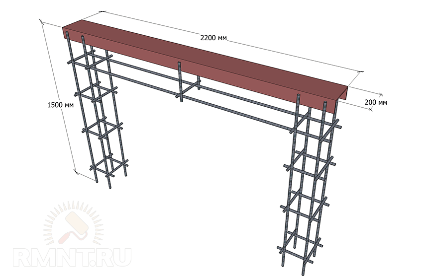 Scheme of the frame for concreting the power frame
Prepare a U-shaped pit for the frame as shown in the figure, prepare a solution based on the calculation of the material (in portions), install the frame and concrete the structure. Freeze time is at least a week.
 Power frame mounting scheme
On the opposite side of the passage, next to the fence post, install a post for attaching the upper rollers and catchers (flashing). It can be concreted, or it can be welded to embedded structures from a corner mounted in a fence post.

Assembly of the structure
When buying accessories, you will be given installation instructions, but sometimes the seller simply does not have it. Let's consider the general case.
1. Weld the adjustable stand to the load frame (at the beginning and end, leaving the necessary clearance) and install the casters on the stand bolts.
2. Weld the platform for the drive to the power frame.
3. Install the gate on the roller bearings by inserting the rollers into the slot of the guide beam. Use a level to level on the adjustable stand. If the stand is not provided, the roller bearings are welded to the mortgage (channel) after checking the horizontal position.

4. Weld the frame of the upper rollers to the mortgages on the pole from the power frame side. Check that the door leaf is perfectly level.

5. Weld to the flashing first the lower and then the upper trap. The lower catcher should be a few millimeters higher than the end roller of the guide. The upper catcher is welded just below the top of the gate.

6. Bolt the end roller into the guide beam.
7. Install and connect the drive and, if necessary, the remote control.

Your gate is ready for operation.


